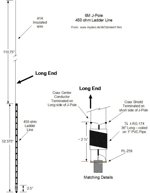
6 Meter J-Pole from 450 Ohm Ladder Line
A quickie project.
Sketch
copied from WB5CXC web page.
The
design by WB5CXC offers a balun made from RG-174 coax and a matching section
of 450 ohm line. Basically you have a half wave dipole in a vertical
configuration fed at the end using a quarter wave section of 450 ohm
line for matching. Easy to erect and
offers a vertical pattern.
Quoting from WB5CXC's web page. "Use a 54 piece
of 450 ohm Ladder line. Cut out 3 inches of the center part of the ladder
line. Solder a PL-259 on the bottom of the Ladder Line (both side of the
ladder line will solder on the ground side of the PL-259 - this is used
for the shorted part of the J-Pole). Cut a 1 PVC pipe 1 1/2 long. Cut
a 36 piece of RG-174 coax. Wrap the coax around the PVC pipe. One end
will attach to the PL-259, the center of the coax will connect to the
center of the PL-259 and the shield of the coax will connect to the outer
portion of the PL-259. Strip the insulation off the ladder line 2 1/2
above the PL-259. Attach the center of the coax to the side that will
have the long wire attached, the shield side of the coax will connect
to the short side of the J- Pole. Connect the Long wire to the ladder
line. Check the SWR, if it is not less than 2:1 in the operating portion
you want to operate, you can tune the J-Pole by moving the tape of RG-174
up or down. Do not move it more than ~ 1/4 at a time." Link
below.
WB5CXC
Web page.
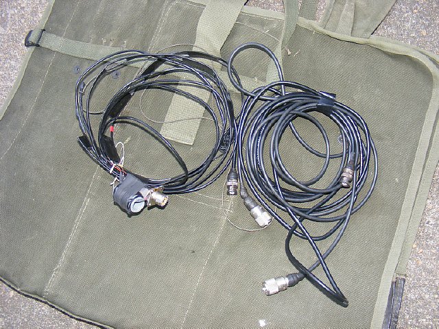
The twin lead J-Pole on the left rolls up into a neat package. Total length is just about 14 feet. The antenna can be suspended from a near by tree limb or use a fiber glass fishing pole etc.

The
WB5CXC design offers a "current" balun made from smaller diameter
coax which offers decoupling of the coax for a cleaner radiation pattern.
You could use ferrite beads slipped over a section of RG-58 but for most
of us the smaller coax is readilly available.
Q.
Do I have to have a balun?
A. No the antenna will still function - the quarter wave stub will
still does its job of matching to the half wave wire.
Additonal
information can be found on DK7ZB's site.
DK7ZB
6 Meter J- pole.
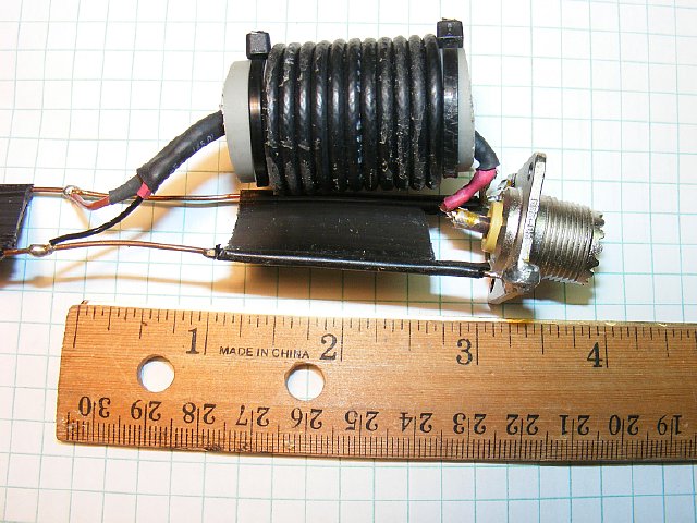
Note that the center conductor of the balun connects to the SO-239 Connector. BOTH sides of the 450 ohm line are soldered to the base of the SO-239 connector. The Center of the SO-239 connector feeds the bottom of the wound balun. The top side of the balun feeds the "long side" of the antenna. PFM.
Be sure that the center conductor of the balun connects to the "long" side of the antenna. You move the Taps up and down the 450 ohm line for best match. PFM
I made a lexan spacer to support the balun. Cable ties hold the balun turns in place.
The 110 inch "radiating" element (wire) connects to the same side of the 450 ohm line as the center conductor of the balun. This is the "long" side.
The balun and spacer block are taped to the 450 ohm line. Simple.
K4CHE
Ready for deployment.
Return K4CHE Index