AS-2259 Modeling and Suggested matching
Now
that I had a fabricated a decent mount for the
antenna mast I continued with several matching tests and
modeling experiments. The object was to arrive at a simple
matching network with one or two components.
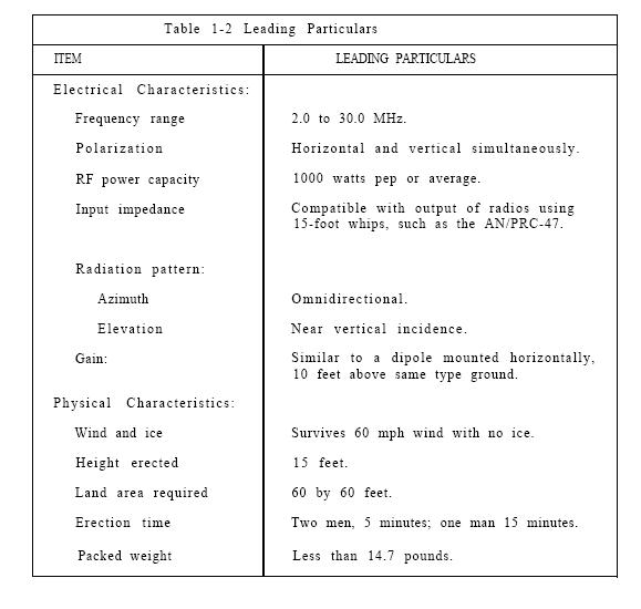
Antenna Specifications
Harris and other companies added that "an
external tuner would be needed"
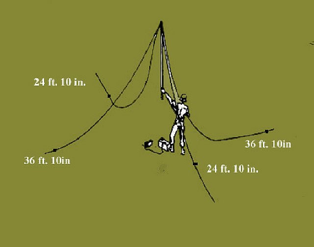 Wire lengths
 Short Wires 24ft.10 in.
Long Wires 36ft.10 in.
Measurements taken directly at the base of the antenna mast
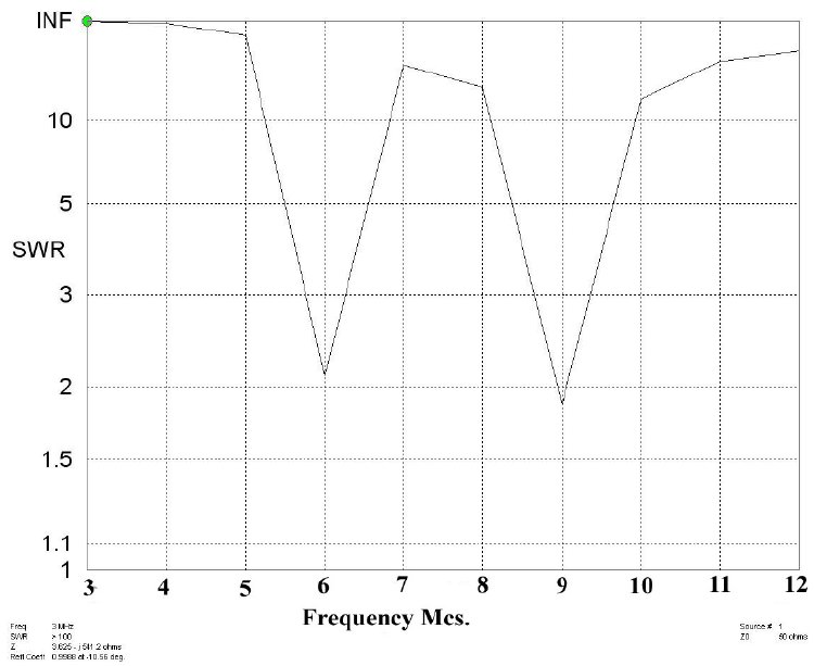
treating the mast and antenna as a "load" resulted in a "natural
resonance" of 6.1 Mc for the longer wires and 9.2 Mc. for the
shorter wires. This Agreed with EZNET.Graph shown below
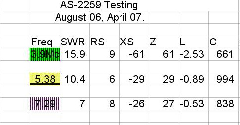
Antenna analyzer readings
Notice that on 3.9 Mc the SWR is 15. The Autek
calculation of "L" is -2.5Uh, this is the value of series
inductance needed to cancel the capacitance to wind up
with a pure resistive load of 9 ohms which would
provide an SWR of approximately 6:1 which would
be well within the range of the typical antenna tuner.
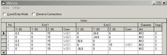
If you like modeling antennas here are the coordinates
that I used with *EZNEC.
Incidentally EZNEC does not lend itself easily to modeling parallel lines.
That's
why there is an extra line in the list above. Its very short and connects
the two sets of wires together and provides a location for the source.
*EZNEC is now supplied with the ARRL Antenna Handbook.
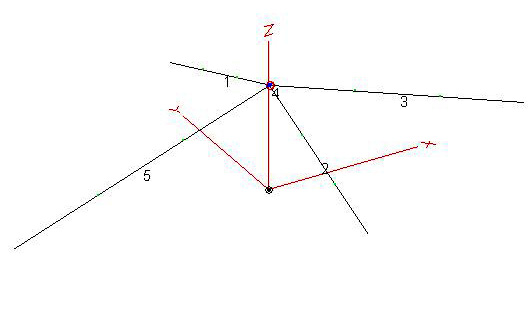
AS-2259 Antenna model
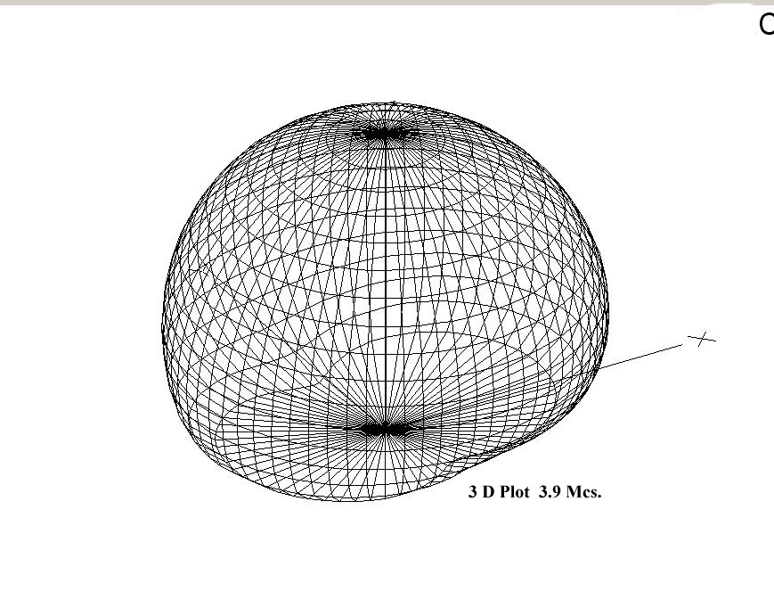
75 Meter 3D Field Plot
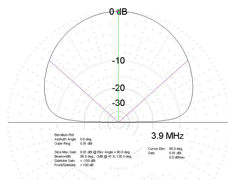
Elevation and gain plot for 75 Meters.
Not much gain.
Note: 75 meter gain improvements. I choose
not to modify the
antenna but the AS-2259 has been modified by several users by
adding additional wire in equal
amounts to the short 24 foot wires
to make them more resonant on 80 meters. In addition a counter poise
wire could be rolled out and positioned on the ground under
all the sections.
I experimented with matching the AS-2259 using simple
techniques
with just one small inductor and one capacitor. After reaching several
successful matches confirmed by field strength--- I would then
use the *"TLW" Transmission Line Program to confirm my matching
component values of capacitance and inductance. It was very easy to just
use a fixed capacitor and a simple inductor for a match in a "L"
network to match.
*"TLW" is now supplied with the ARRL antenna
handbook.
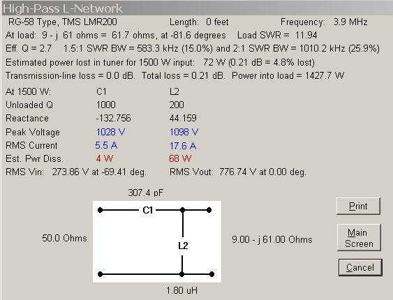
3.9 Mc. Hi Pass L Matching Network
In this case a cap value of 300 pf and a
inductor of approximately 2 uH provides
a match on 75 meters.
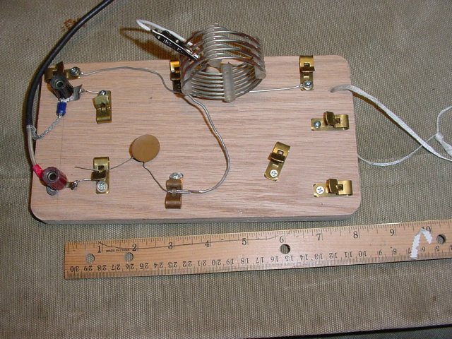
3.9 Mc. Hi- Pass L Network test board using
Inductor with tap and 300 Pf Cap. The tap is
fairly critical, be prepared to move the clip around.
Link at the bottom for more matching tools.
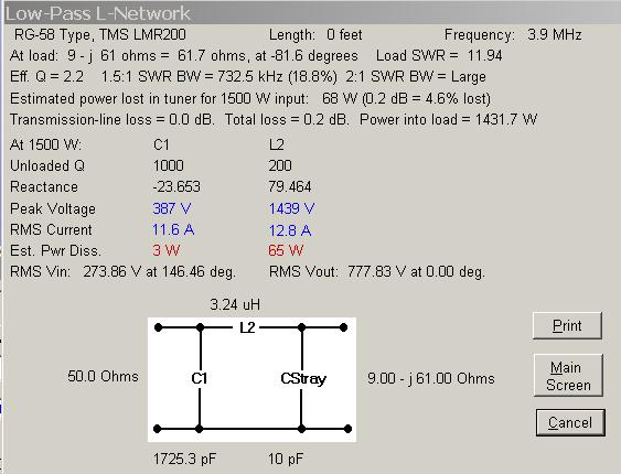
3.9 Mc. Low- Pass L
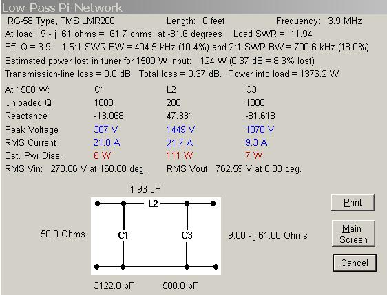
3.9 Mc. Low Pass Pi-Network
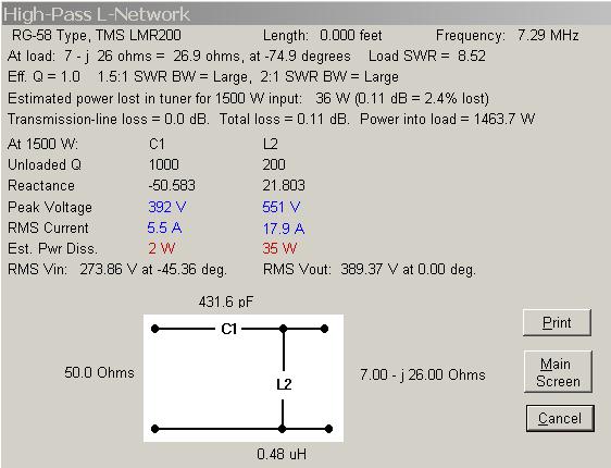
7.3 Mc. High-Pass
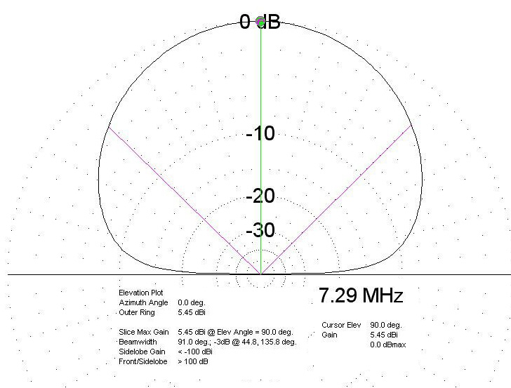
40 Meter plot, more gain.
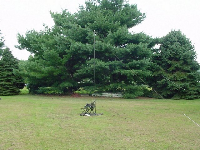
"Test Range"
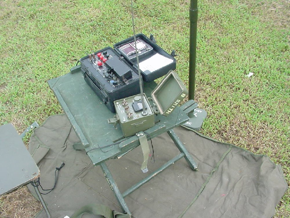
No problem using the Delco 5300
on 80 meters without a tuner.