The BC-474 transmitter section was "designed" to be powered by the hand cranked GN-44 with the receiver option of being powered by the GN-44 via the FL-10 filter or by a battery similar to the BA-48. On these pages we will attempt to offer some ideas of alternative methods of powering the set as well as fabrication of connectors.
The
Mission: Get the set off the shelf and operational into the field.
 Please
Note: Numerous Circuits and Options are shown on these pages
as well as connector fabrication suggestions. I suggest that you study all
of the options before making a decision. The purpose of these pages is to
provide different methods for powering the set.
Please
Note: Numerous Circuits and Options are shown on these pages
as well as connector fabrication suggestions. I suggest that you study all
of the options before making a decision. The purpose of these pages is to
provide different methods for powering the set.
CLICK to enlarge
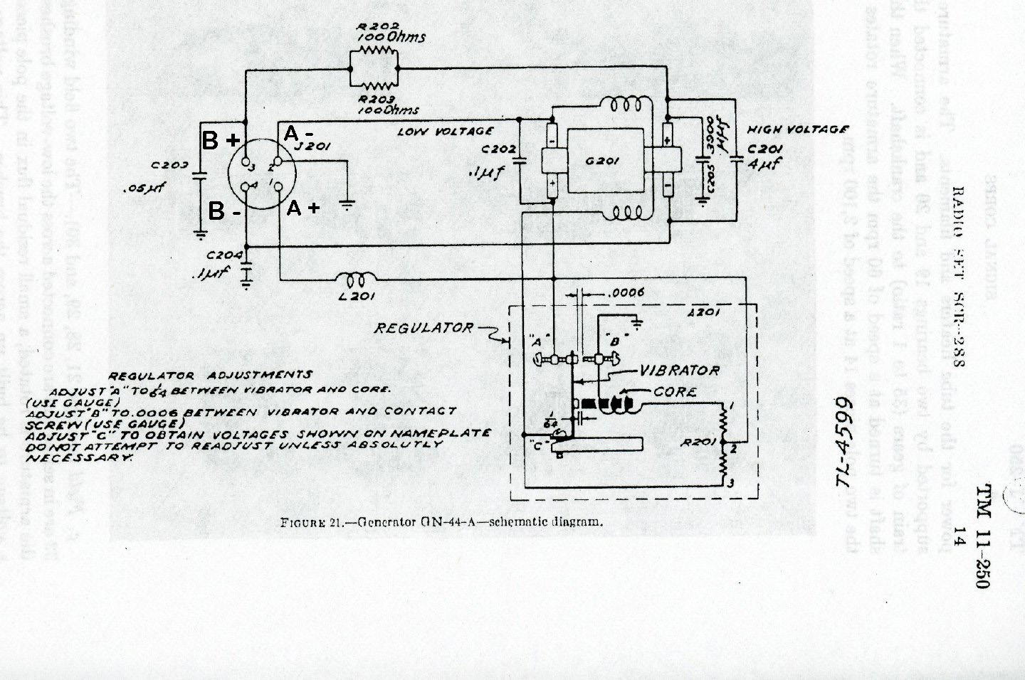
In order to provide proper bias to the receiver audio section the HV section of the power supply B - (B minus) must be above ground. The GN-44 hand crank generator diagram shown above demonstrates the B- (B minus) wiring.
WARNING:
Do not apply High Voltage direct to the set by grounding the B
- (B minus) to the chassis. The final receiver
stages will not be properly biased and damage to the audio transformer
is possible.
WARNING:
Do not apply 6 volts to the receiver filament chain the receiver uses
1.5 volt filament tubes. The transmitter uses 6 volt tubes.
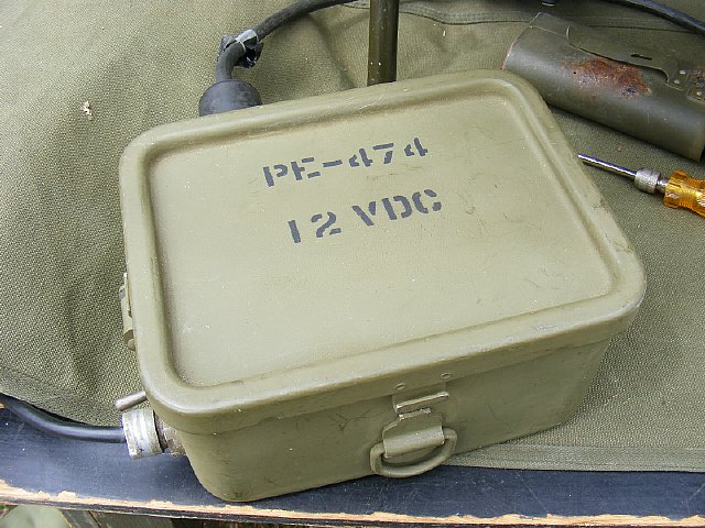
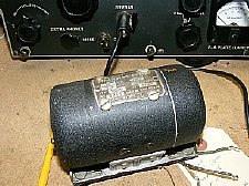
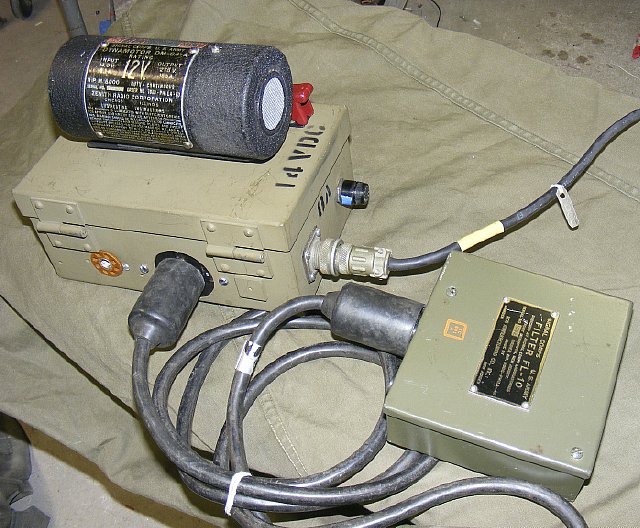
A small 12 volt power
supply is handy for meets and rallies. Very handy if you want to run the
BC-474 receiver continuously as visitors like to hear "short wave"
and especially CW signals. The box above contains a switching power supply
"borrowed" from one of the older 2 way VHF radios and with a
additonal 6 volt regulator is designed to work in conjunction with the
BC-474 FL-10 filter described below.
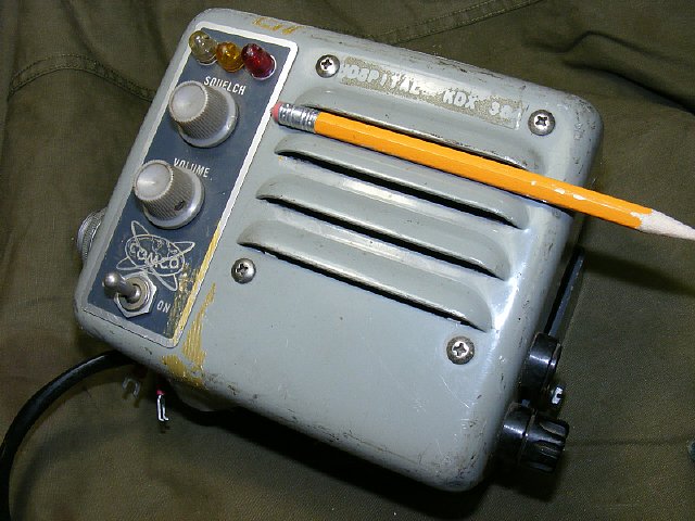
One of my favorite sources for switching HV supplies is the COMCO two way radio line. Shown above is a typical control head/speaker often seen at ham fests. You pick it up and think you have a heavy speaker but inside is a HV supply.
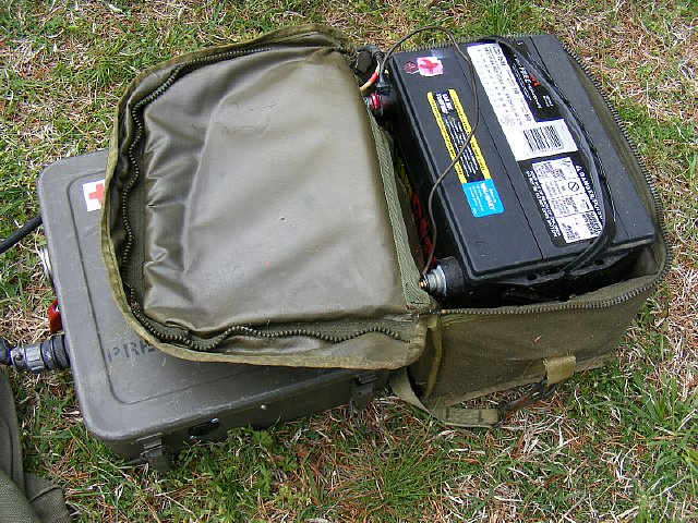
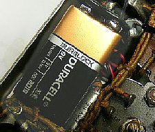
A fairly small 12 Volt wet cell from Wally World automobile section - - - about 3 times the size of a lawn mower battery. Note the side bolts and knurled nuts to hold wire terminals.
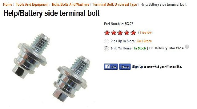
Typical side terminal bolts - - these were on the AutoZone site. I drilled and tapped mine to hold smaller 8-32 bolts and knurled nuts.
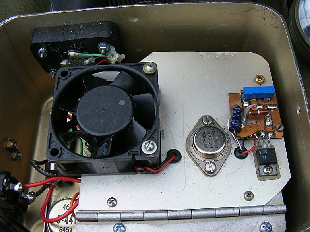
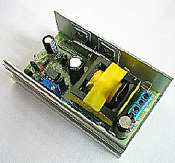
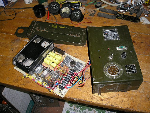
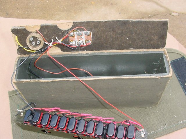
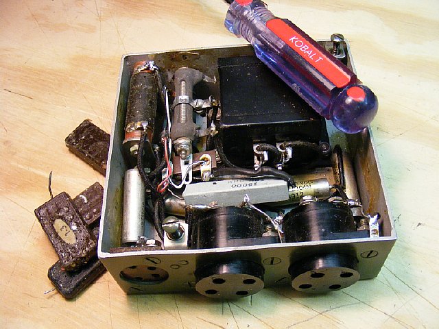
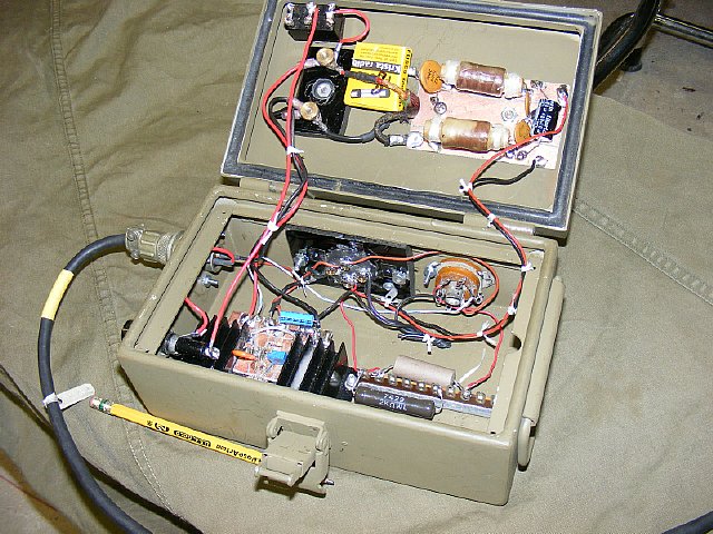
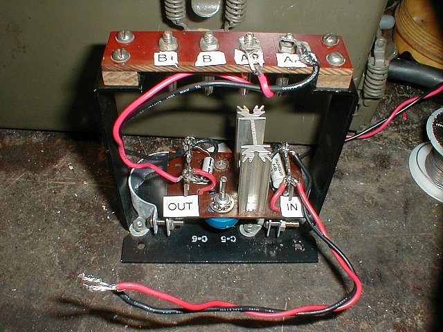
The enclosure lid cover has been set aside and the interior of the power supply exposed. The home brew regulator on the right is for 6 volts. When the power supply is running continuous I often lift the lid slightly for cooling. Note: The BC-474 transmitter filaments require 6 volts however the receiver filaments need a 1.5 volt supply. This particular power supply is designed to replace the hand cranked GN-44 and feed the FL-10 filter which in turn powers the transmitter and receiver. More info below.
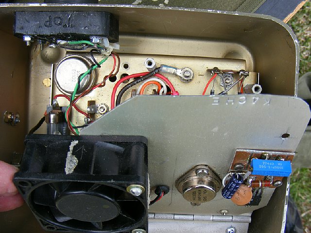
A
hinged upper deck allows easy maintenance and to access the original COMCO
power supply. On top of the lid is a cooling fan and a regulation circuit
for the 6 volt filament. This supply is used in conjunction with the FL-10
filter assembly which "smooths" the hand crank generator HV
and also provides filament and high voltages for the receiver.
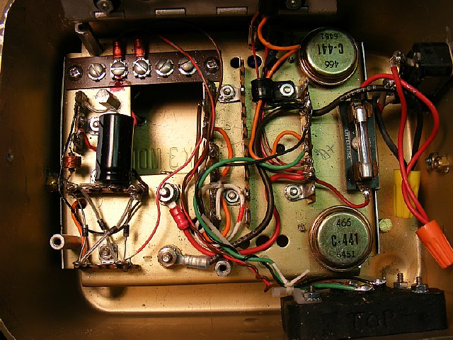
I often use simple "wire nuts" for primary 12 low voltage connections - - they allow easy disconnect for maintenance. Easy on and easy off. Wax on wax off. Simple.
Two
Germanium PNP- power house-rugged- bullet proof transistors provide the
switching. Since a transformer is utilized it is possible to have the
B minus isolated and be above ground as well as filter capacitors etc.
This "floating" ground will satisfy the BC-474 receiver bias
requirements. The BC-474 bias can be a problem when using external
power supplies that do not have a floating B minus configuration. More
info below
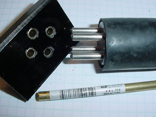
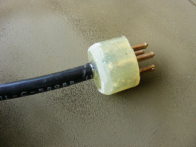
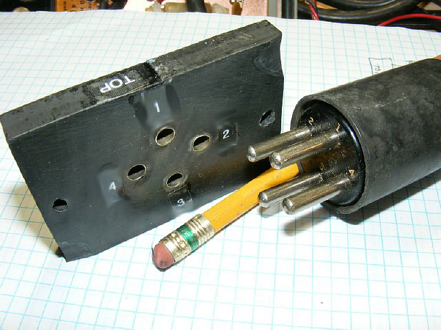
The
black power connector shown above (rear view) was fabricated using brass
tubing and epoxy. Not too pretty but very functional. The Kcerb rule:
"If you can not find a connector then fabricate one."
"Improvise
- Adapt - Overcome"
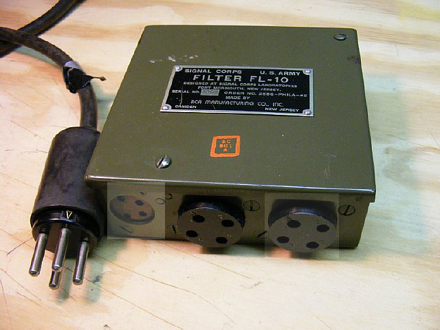
Outside view of the fabricated connector.
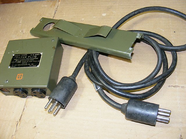
Some items to look for at a Military Rally or a Ham fest.
FL-10 Filter, CD-125 (Generator Cord) with male connectors. The BC-474 battery compartment cover is also shown.
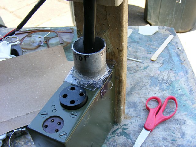
Here is another "chassis" connector on the left that I fabricated with black phenolic and brass tubing.
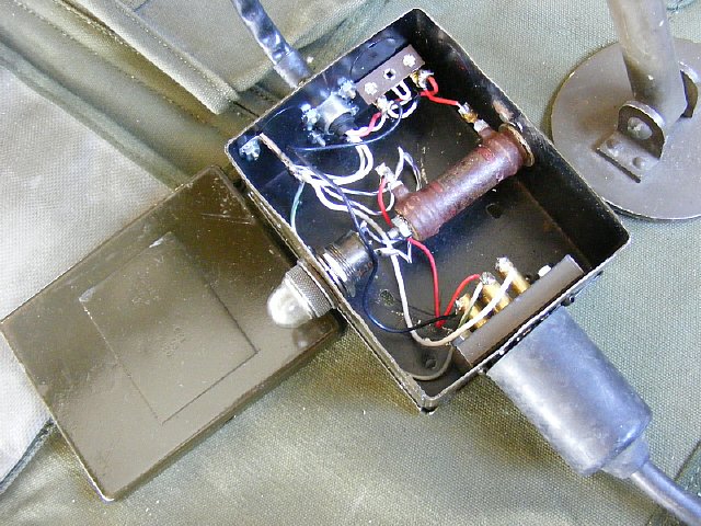
The connector was mounted in this enclosure. The enclosed circuit was used to convert a GN-45 cable for use on the BC-474.

Not
exactly "correct" but the GN-45 shown above makes for an interesting
display and powers the BC-474. A light on the "k4che conversion box"
illuminates when up to speed.
Click
below for more information on converting the GN-45 for use on the BC-474.
GN-45
BC-474 Conversion.
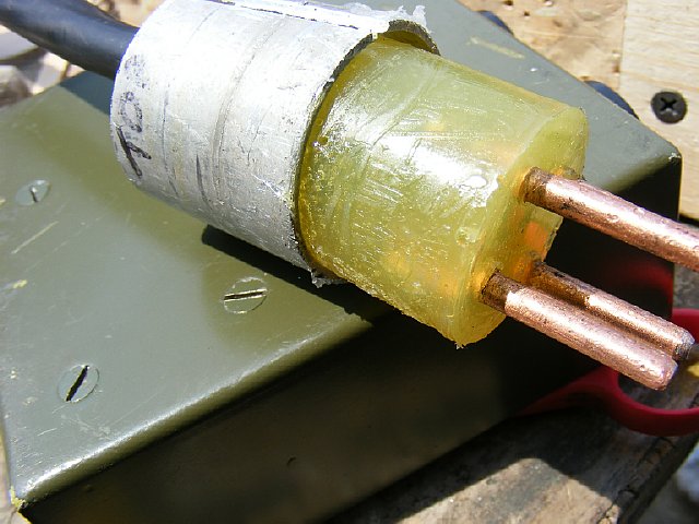
A male "fabricated" connector. A short portion of round aluminum tubing was the mold. Grease the mold prior to pouring in the epoxy.
I used the FL-10 filter as a guide and made pins from heavy copper wire. Grease well and use a thin piece of plastic as a barrier. Solder the cable to the pins and then fill with epoxy. Its a simple 30 minute project.
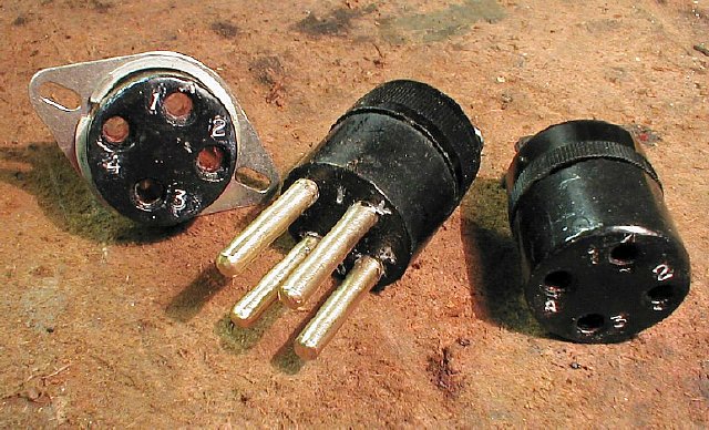
Here are connectors fabricated by Master Craftsman Mark KD3ZK - - he even numbered the pins.
The FL-10 filter was used to reduce noise from the GN-44 and to supply proper voltages to the receiver via dropping resistors The generator cable plugs into one large connector (either connector) and then the BC-474 chassis main connector plugs into the other. The smaller connector is for receiver power. Schematic below.
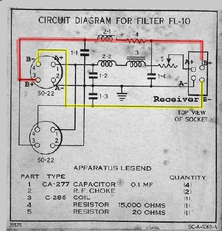
FL-10 filter diagram. Note that the B minus is above ground. Also note that the generator low voltage of approximately 6 volts (A+) enters at pin 1 on SO-22 and then is dropped by a 20 ohm variable resistor (5) to provide 1.5 volts for the receiver filaments. The receiver B+ is supplied via a 15K dropping resistor from the GN-44 high voltage. The 20 ohm wire wound variable resistor is perfect and it is easy to adjust the receiver filament voltage of 1.5 volts.
WARNING: Do not apply High Voltage direct to the set by grounding the B - (B minus) to the chassis. The final receiver stages will not be properly biased and damage to the receiver audio transformer is possible. In addition audio output will be slightly distorted as the volume/RF gain control will not function. You BC-348 receiver fans will recognize this problem.
WARNING: The BC-474 receiver filaments require a voltage of 1.5 volts - Do not apply 6 volts.
Another
favorite radio to look for at a hamfest. GE made these sets for "Low
Band" and "High Band" and they are often listed on ePay.
The power supplies are very rugged and can run continuously.
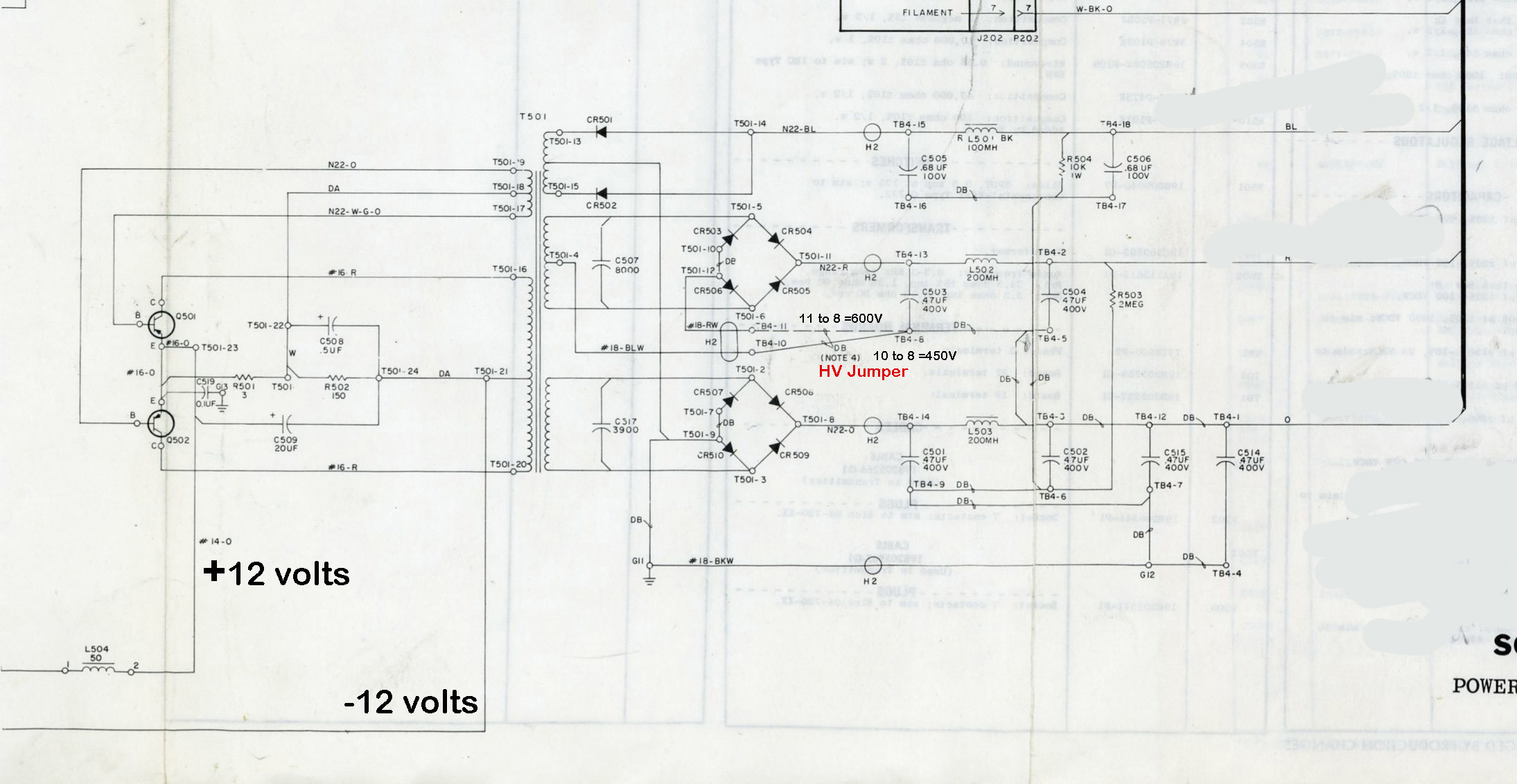
CLICK to enlarge
A typical GE Exec power supply.
Above is an example of a "repackaged" GE mobile radio supply. Filament regulators were added and the supply was used to power the BC-1306. Constructed by the famous military radio Collector Bud, WA2AUI.
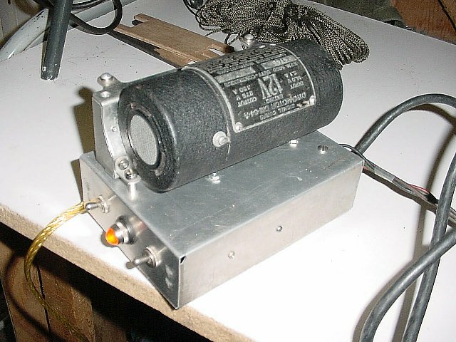
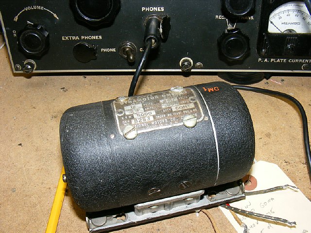
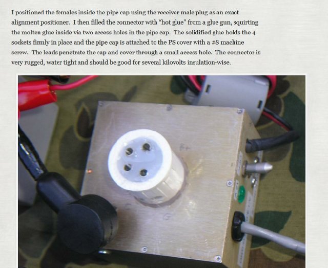
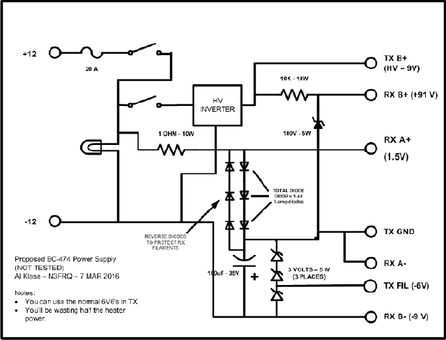
A very neat dynamotor package for the BC-474 by Al, N3FRQ. More info below.
CLICK
to enlarge N3FRQ
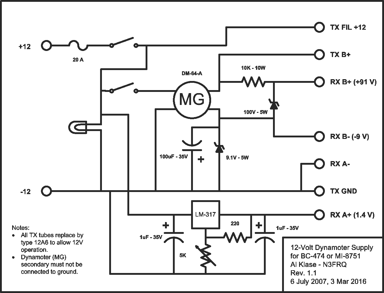
Diagram
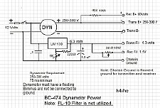
"Floating"
B minus Dynamotor needed.
A suggested Dynamotor power supply by Al N3FRQ when the
FL-10 filter is not utilized. Voltages are regulated. More
FL-10 info below.)
Al
-N3FRQ used a 12 volt dynamotor (DM-64-A) found at a hamfest that is used
in the BC-923A FM military receiver. The DM-64 dynamotor audio stage.
" I replaced the 6V6's in the TX with 12A6's. The
rig pulls about 4.4 A from a 12-volt battery in AM, 4.0 A CW key-down,
2.8 A standby, and 2.3 A receive only." Note the zener network used
to provide proper bias. Proper bias is needed for the receiver audio
stages.
Al Klase BC-474 dynamotor supply notes: "I've been playing with my MI-8751 (original Swedish version) getting ready for future events. I discovered I had a mistake in my dynamotor power supply design. I had the RX and TX B-'s connected together. This shorts out the 800-ohm resistor in the RX B- that provides bias for the audio-output tube and RF gain on CW. (You don't notice this too much in AM.) I've added a 9-volt Zener in the dynomotor B- line. This regulated voltages swamps the 800-ohm resistor, and everything works five. Drawing attached. I don't know if you were contemplating building one of these or not. The DY-64-A is rated at 275 volts 150mA with 14 volts in. I replace the 6V6's in the TX with 12A6's. The rig pulls about 4.4 A from a 12-volt battery in AM, 4.0 A CW key-down, 2.8 A standby, and 2.3 A receive only. So my 17 AH battery will run it for a while."

CLICK
to enlarge
"Floating"
B minus Dynamotor needed.
A another circuit utilizing
a Dynamotor and the FL-10 filter. The LM138 regulator is rated for 5 amps.
An LM317 (1.5 amp rating) can also be used. The dynamotor needs to have
a floating B minus. (4 wires or contacts)
Total current draw for the 4 receiver filaments (1.5 volt tubes) is .25 ma. Three (3) of the receiver tubes draw .05 amps and one tube (V4) draws .1 amps.
Total current draw for
the transmitter filaments (6 volt tubes) is .45 X 3 = 1.35 amps
An interesting note: The average adjustable voltage
regulator when used for the filament supply needs approximate 1.5 volts
input above the output. In other words for a regulated output of 6.3 volts
then approximate 7.8 volts is needed for the input voltage to the regulator.
If this keeps you awake at night you can use a Mouser LD1084V a 5 amp
low drop out regulator which only requires approximate half a volt ) above
the input to function.*
* Many thanks to Al N3FRQ for the suggestion.
The receiver bias problem can be easily solved by just running the receiver from a BA-48 or similar battery. Fair radio has been selling dead or weak BA-48 batteries and they are easy to rebuild. And the good news is the existing connector can be used. Details on rebuilding a BA-48 can be found at:
http://k4che.com/BA48/BA48pg1.htm
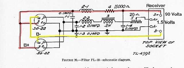
FL-10 Filter schematic that I have added a few notes. Please note that the resistor in the A plus line (1.5 volts) is a 20 ohm adjustable. Your 6 volt low voltage source enters the circuit on the LEFT side at Pin 1(either SO-22 connector) and then is distributed to the transmitter filament string at the other pin 1. The pin 1 circuit then continues and feeds the receiver A plus (1.5 volts) via a a filter choke and a "adjustable" 20 ohm 10 watt resistor.
Just like any older piece of WWII equipment several capacitors had to be replaced in the FL-10 filter.

The ideal WWII
"field operation" configuration would be to run the transmitter
off of the GN-44 and the receiver would be battery powered. In
this case the FL-10 filter would not needed to smooth the HV output
of the generator and to provide voltages to the receiver as the receiver
is battery powered.
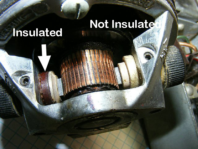
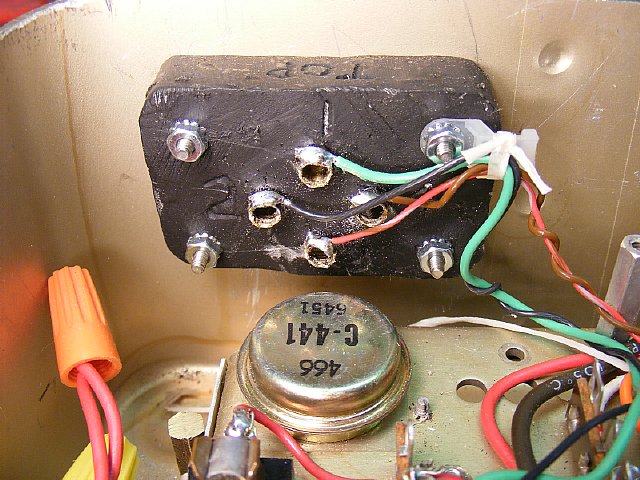
When considering a dynamotor for powering the BC-474 receiver and transmitter
the simplest solution is to have a floating" B - (B minus)
but be aware that many of the dynamotors do not have the B
- terminal insulated above chassis.
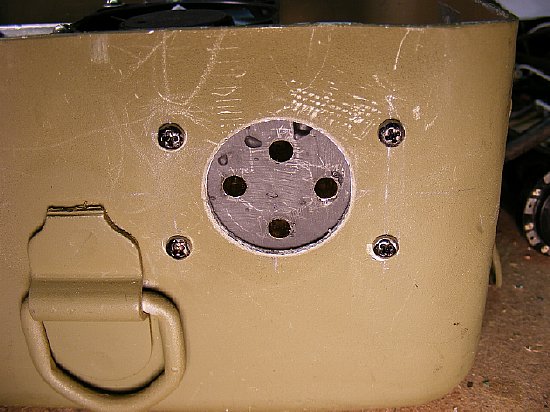
The terminals of my hamfest acquisition a DM-53 are shown above. The left
side is high voltage + (plus) and the right
side is - (minus). The left side is insulated
but the right side is not.
Provisions for bias will have to be made
for proper receiver stage operation when using this type of dynamotor
on a BC-474. More
info below.
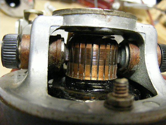
This
DM-25B dynamotor utilizes insulated terminals for each input and output.
The dynamotor is rated for 250 volts at 50 ma and during bench testing
it provided enough power to run the set. Even at 10 volts there was sufficient
voltage to run the receiver and transmitter at reduced power. Below 9
volts input the modulation on AM drops off but CW operation is OK and
is sufficient for demonstrations at a military meet or rally.
DM-25
dynamotor.
Here is a
PDF file of a dynamotor list downloaded from the amfone.net site. Author
unknown.
Dynamotors
and Hand Generataors for
the Experimentor
Here is a link to Ray Robinsons Dynamotor
list.
Ray
Robinson' Site Dynamotor list
Robert Downs suggested
that there are some possible 12 volt candidates that have a isolated HV
B minus output.
12/14 V dynamotors with floating B- brushes are: DM-34-A (BC-604) and 211042 (TCS) but output is only about 220 VDC from 14VDC in. 21215 (RU) 300VDC/0.163A from 12VDC in. 21454 (GF/RU) but output @ 14 VDC in is 425 VDC DY-10/ARC-4X Output 360 VDC/0.160A from 13VDC in. That's all that I can think of in 12 to 14 VDC input. I have at least one of those except for the 21454 (assuming I can find them). The DY-10 has a bent fan according to my database but I may have a DY-9, too.
My fabricated BA-48 connector using brass welding rod material as tips and poured epoxy as a base. Painting with black fingernail polish which sticks fairly well to the epoxy will give the connector a finished look.
Speaking of connectors N6CC fabricated this female version of the BA-48 connector. This type of connector would be needed when fabricating your own version of the FL-10 filter or if you built home brew battery pack.
http://www.n6cc.com/grc-9-grc-109-receiver-battery-power-supply
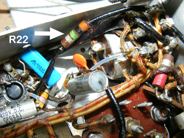
What
ever method of power you choose if you are worried about the bias voltage
and want to check it - The R22 bias resistor is easy to locate. Check
the voltage on the Tube side of the 1 megohm resistor- it should be around
minus 9 volts with respect to the chassis.
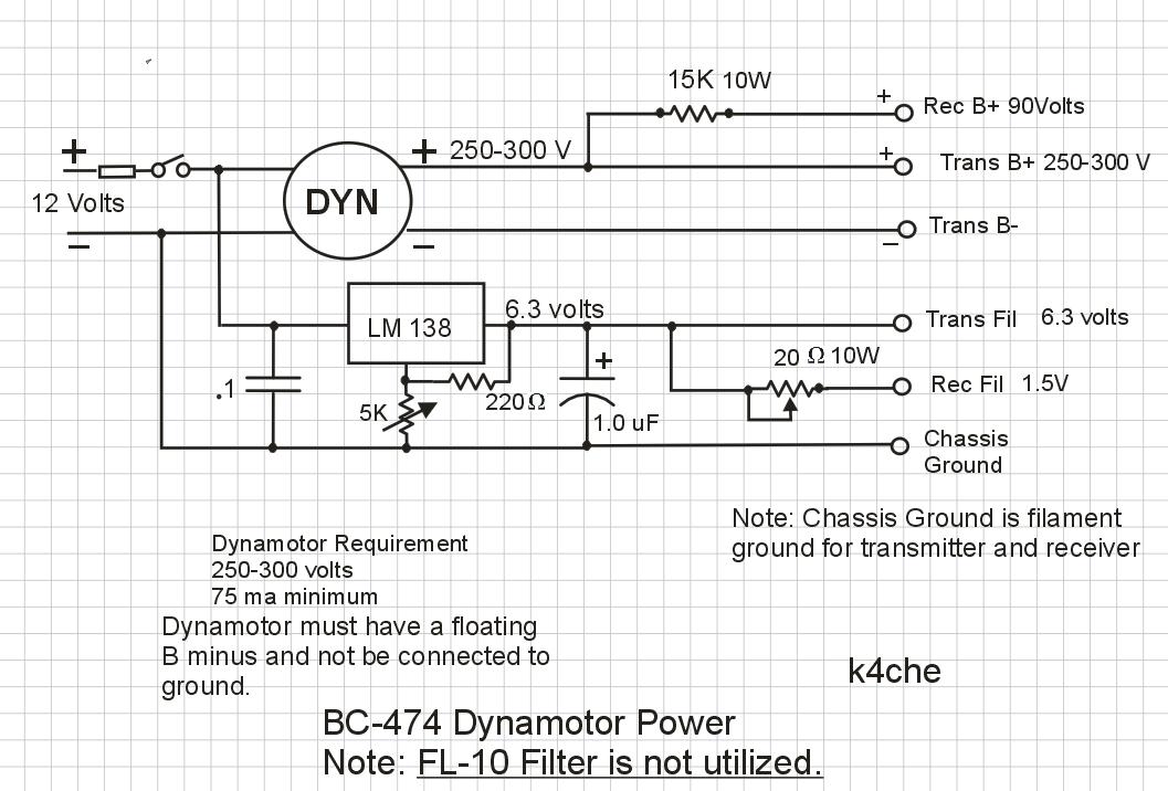
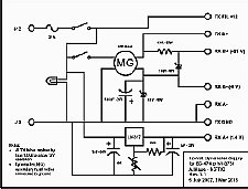
CLICK to enlarge
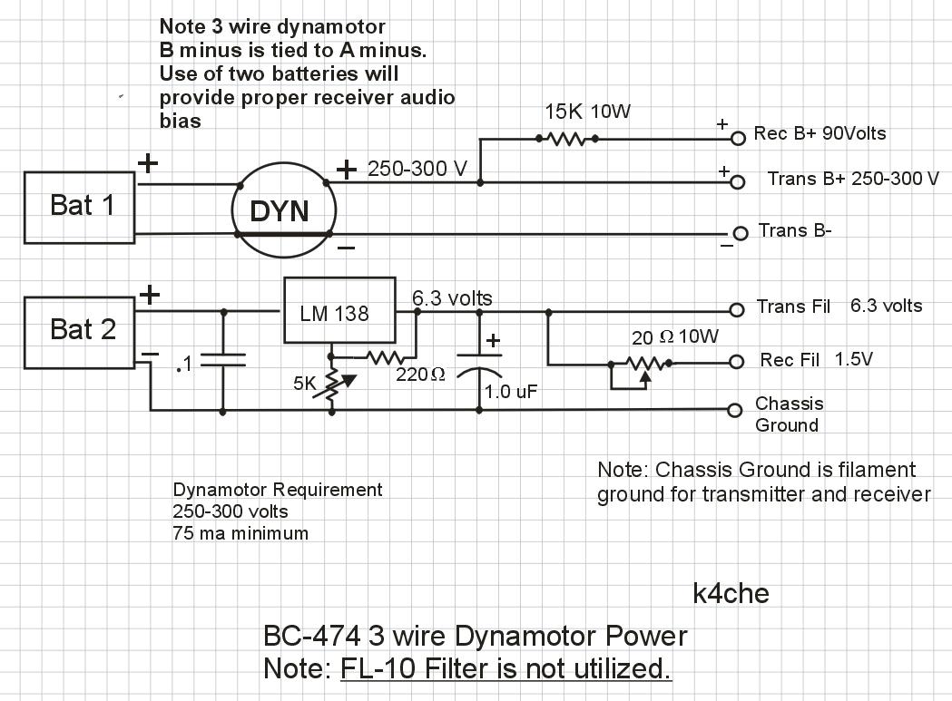
Diagram above: "Floating" B minus Dynamotor. The FL-10 filter not used.
Dynamotor circuit using a "floating " dynamotor but only one regulator circuit is used for the transmitter filaments and dropping resistors are utilized for the receiver high voltage and filament power. (This is the same system using dropping resistors as the FL-10 filter) Fixed resistors can be used in lieu of the 20 ohm adjustable, start with 10 ohms.
CLICK to enlarge
Grounded B minus Dynamotor
Yet another diagram this one uses a Uses two (2) 12 volt batteries and this battery isolation will provide a "floating" ground and proper receiver bias will be established. You can use a 3 wire dynamotor (grounded B minus) or perhaps an ePay inverter that has the output B minus tied to the input A minus. Confused yet?
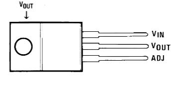
Typical
pin out for a regulator in a TO-220 configuration.
A suggested method of mounting a TO-220 style regulator.
http://k4che.com/RegulatorPadmount/reg
Check
out the voltage regulator caluator link below.
http://www.muzique.com/schem/lm317.htm

Another
possible solution for HV. Available on ePay. Advertised as a DC input
12 to 24 to DC 200-450V 70W "high voltage converter" boost step
up power supply. But the battery input A minus and the HV output B minus
are tied together and provisions will have to be made for bias.
I have tested this supply and it certainly will power the set and will
do so well below 12 volts. Keep in mind that the output B- (B minus) is
tied to the input A minus. So provisions for bias have to be made. BUT
there are solutions shown below.
Here
are a couple of videos that I made during bench testing of the above inverter
supply.
Grounded
B minus Inverter or 3 wire Dynamotor utilized.
Another
circuit by Al N3FRQ but this version has not been bench tested .
The builder will probably sub a 6 volt and 3.3 volt zener in the TX FIL(-6V)
and RX B- (-9V) voltage circuits as the 3 volt zener is not readily available.
Using
the 9 volt battery to provide receiver audio stage bias allows
the use of a "non floating" dynamotor or a imported ePay switching
inverter.
Q.
How much drain does the BC-474 bias circuit impose on the 9 volt battery?
Ans.
Less than 5 ma. (.005 amps)
Q. I am worried
about the battery running down and then I lose my bias and possible damage
the audio transformer.
Ans.
When using your volumn/RF gain control listen carefully - - If the audio
starts to degrade your battery is getting low and it is time to change.
Q. Does
the bias have to be exactly 9 volts? See below.
Ans.
NO
Q.
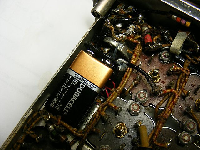
I don't think I can fit a 9 volt battery into the bottom of the reciever.
Ans.
Don't be a weeny - give it a try. But if all else fails use a smaller
battery. SEE BELOW.
Smaller battery packs are available. You can use a lower or higher bias voltage by a couple of volts. Many smaller battery packs are available for voltages less than 9 volts.
A 9 volt battery can be made smaller.
With the outer case and connector removed the size is considerably smaller. It should be noted that in this configuation it is very hard to test the battery on your tongue.
By removing 2 cells you can fabricate a very small 6 volt battery which has even smaller demensions and should be more than enough voltage for receiver audio bias.
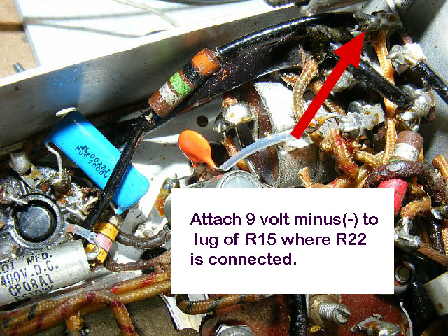
Attach the battery minus to the lug of R15 as shown and be sure and ground the positive + lead of the battery to the chassis. Do not disconnected the R22 the brown black green resistor. But you are not done see below.

9 Volt
bias battery installation. Connect battery minus to R15 lug 3. Positive
of the 9 volt battery to chassis ground. Locate the white wire that runs
from R15 to TB1 and disconnect at TB1 to isolate the bias line and prevent
draining the battery. Insulate the end of the disconnected white wire.
OR
- - - - -
Just disconnect white wire at
TB1 Lug 1 and connect the 9 volt battery minus to the end of the wire
with positive going to chassis ground. Do not
change anything at R15 lug 3.

There
is a white wire running from the R15 lug to TB1 it is dressed along the
"rear" of the receiver chassis. When using an internal 9 volt
bias battery mounted near the front panel mounted R15 - - - disconnect
this wire from lug 1 of TB1 and insulate the end with spaghetti. (The
white wire is dressed along the rear of the receiver chassis.)
OR
You can mount your battery near the rear of the chassis. Locate the white wire and disconnect at TB1 and connect bias battery.
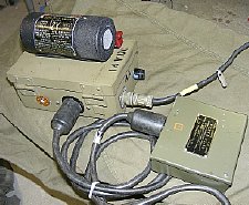
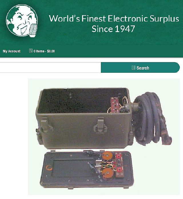
K4CHE BC-474 Dynamotor Supply.
Another version of a DM-64 dynamotor supply. Note the attached BC-474 generator cable and FL-10 filter. This particular supply will furnish HV to the transmitter and has an internal regulator section for 6 volts. The FL-10 will provide the reduced voltages to the receiver. The extra connector on the dynamotor chassis is for any aux equpment that needs to be powered.
Another connector was fabricated for the DM-64 supply.
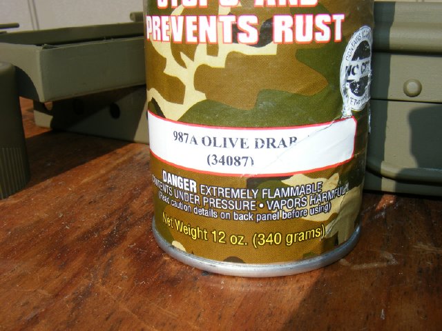
I've
had a lot of question about paint. Aervoe makes great WWII paints. One
of my favorites is the 987A Olive Drab.
Often
sold at military meets and rallies.
K4CHE Dynamotor Supply
Interior of the DM-64 dynamotor supply. The top section contains the "noise" filter. The bottom section houses the 6 volt regulator, main connector (fabricated) and a "auxiliary" connector. The terminal board to the right provides dropping resistor connections for any aux equipment via the 8 pin octal connector.
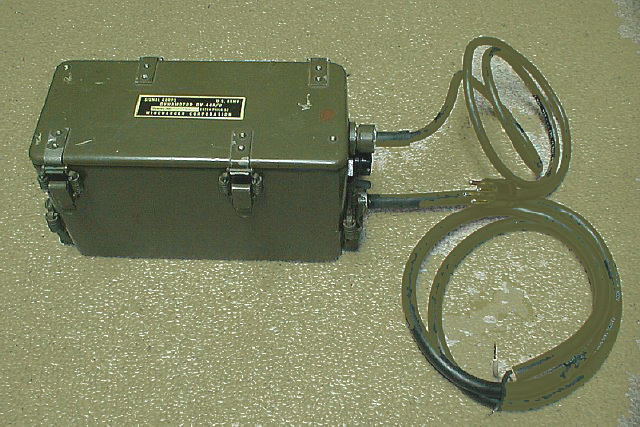
Photo by KD3ZK
Mark KD3ZK fabricated a nice supply using a DY-44 case. The case has a nice weather proof On-OFF switch and a internal board for wiring.
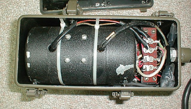
photo by KD3ZK
A TCS dynamotor which has A floating B- makes a perfect fit.
Fair Radio has the DY-44 cases NOS but no dynamotor.
KD3ZK photo
Mark used the existing distribution section to house the filament regulator and wiring.
Click
to enlarge K4CHE
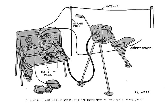
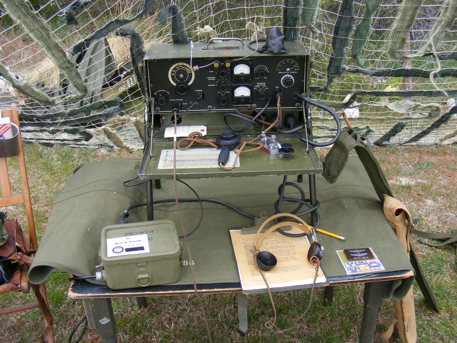
Complete
station fully powered. In this case the receiver and transmitter are powered
via the FL-10 (under the right side of the set) which is connected to
the switching supply on the table using the standard 4 pin generator cable.
I usually hide the switching power supply under the table near the battery.
Return
to K4CHE Index
The
BC-474 was on a operational display during Ft. Miles 2015