.
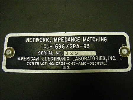
This tuner is part of the GRA-93 Antenna Kit. Very little
information has been pubished on this system. I would appreciate any information
etc.
The Tuner was designed to feed either a 60 foot or a 120 foot wire in various configurations. I acquired this tuner at Gilbert two years ago. Thanks Jeff.
.JPG)
Three variable capacitors are selected by a front panel switch and have dial indicators. The front panel measures 7 inches by 5 inches. BNC input and binding post output.
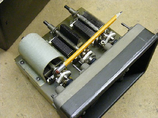
One of the variable capacitors has a cover for high voltage situations?
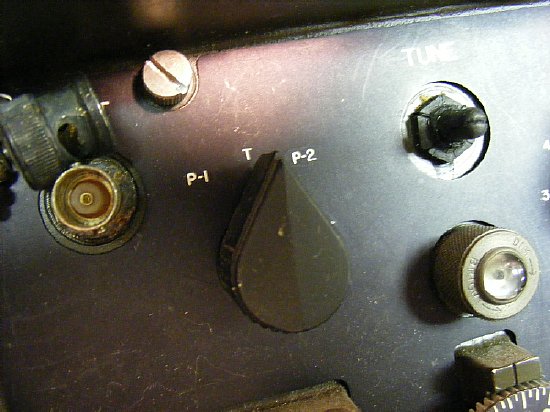
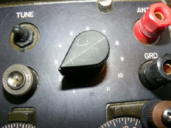
One of the variable capacitors is selected by this switch. P-1 and P-2 are preset positions where the capacitor is set and then locked into position. The T position is for variable tuning. There is always one variable capacitor in the circuit and it is connected between the Input and the Output connector. So basically you have the capacitor between the input and the output and then you have a tapped coil on the output selected by a rotary switch.
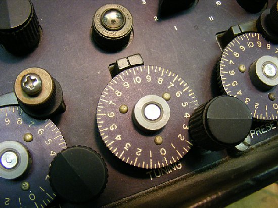
Dial
indication of 10 is maximum capacitance of 330 pf.
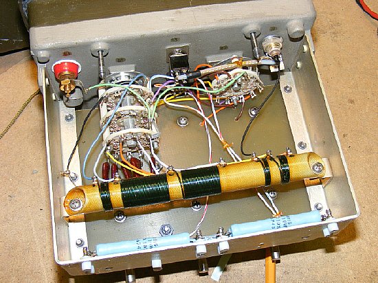
Fairly rugged construction. 30 to 40 watts maximum power.
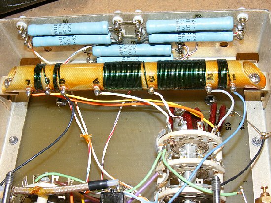
Power resistors provide a dummy load of 75 ohms when Tune is selected a tap is provided to provide voltage to the Tune light. Why 75 ohms, I have no idea.
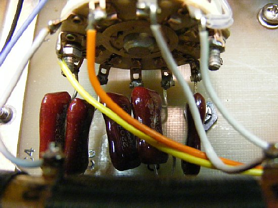
A 11 position switch selects different taps on the coil (pos 1-6) and positions 7-11 select fixed capacitors.
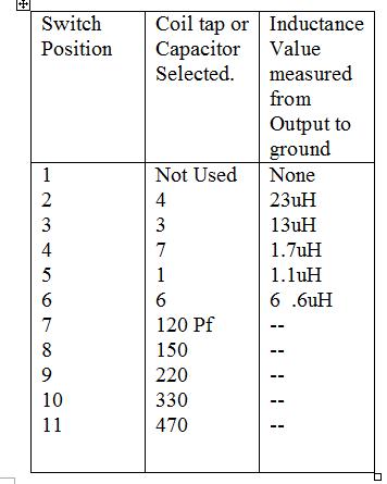
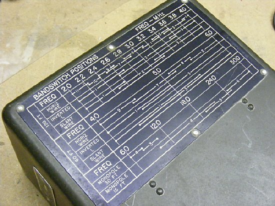
Coil chart and actual measured values.
Various
fixed capacitors are selected for switch position 7-11.
My rambling notes.
CU-1696/GRA-93 Source: Gilbert 2012.. The Tuner is part of a field antenna kit. An Internet search results in finding a few mentions of a "Field Antenna" test in Vietnam year 1967. The tuner was designed to tune a 120 foot or 60 foot wire arranged in various configuration and to reduce the high impedance of the end fed wire to 50 ohms. See chart on top of case. Lowest freq was 2.0 Mcs (two Mcs)and highest was 30.0 Mc(Thirty Mcs) Note: The 120 feet is a half wave on 75 meters and may be difficult to load due to the high impedance. The 60 foot length may be difficult on the high end of 40 meters. The tuner looks like it would be perfect for low powered radios such as the PRC-71 or the SG-715.
Basic design of the tuner consist of a tapped inductor ( several wire wound coils), a wafer switch for selecting coil taps on the first positions and then fixed capacitors on positions 7 - 11 which are connected from the output connector to chassis ground. A variable capacitor is permanently connected from the Input to Output and is not switched. Overall the tuner looks like it would handle 50 watts max. There is a TUNE switch and indicator. The indicator is a small peanut bulb ( Bulb number is GE 328) with a standard filament( not neon) and is rated for a low voltage of 6 volts and 200 ma. The load resistors mounted on the rear panel are 100 ohm 10 watts and are arranged in parallel and series to provide a 75 ohm load (note not 50) when TUNE is selected. The TUNE bulb taps off of one of the pairs resistors.
Coil Information: The inductor has 7 taps for the various coils(5), however all the coils are not connected in series. Coil group 1-2, 2-3, 3-4 are in series and the coil groups 5-6 and 6-7 are in series. Inductor Coil Tap 1 on the first group is grounded by the switch and tap 5 on the second group is grounded by a black wire to the chassis.
A variable capacitor is selected by a front switch and it is permanently connected from the Input to the Output and is not switched. Each capacitor is the same, the 3 position switch marked P-1, T, and P-2 selects one of the three capacitors. P-1 and P-2 can be "preset" to a fixed setting and the knob is tightened to hold that position. But all the capacitors do the same thing they are all the same value and only one is used at one time. Note. 10 on the dial corresponds to maximum capacitance. Zero is minimum. The Center position of the three position switch is marked "T" and is used to select the center variable and tune. The variable capacitors are all the same and measure out to be approx. 20 to 330 pf. However any of the 3 variables can be selected, they are all the same and all wired the same.
The #2 variable capacitor has a insulated cover on the inside possibly to give the option of being selected in a very high voltage situation when possible arc over to the case existed. A possible use for the one of the "extra" caps is to allow position 1 to select the cap to ground, wires would have to be cut etc.- or perhaps have alligator clips to insert the extra capacitor. Wafer switch construction. The wiper is on one side of each section with selections on the other side of each section. The wiper connects through the wafer section to the other side. The 11 position rotary wafer switch is used for the coil taps and various fixed capacitors. Note: Position 1 is not used and when it is selected all that is in the circuit is the Variable capacitor between the Input and the Output connector. This measures out to be approx. 35 pf at a minimum setting to 380 pf at the maximum setting, some extra capacitance is due to stray value in the circuits. However position 1 is used on the chart for several frequencies so probably best to leave it as is and not use it in any modification. Position 2 selects coil tap # 4 Position 3 select coil tap #3 etc See chart.Note that this tuner with the Variable capacitor going from input to output and not being switched and the tapped inductor from output to ground is not the typical configuration for a "long wire" tuner.
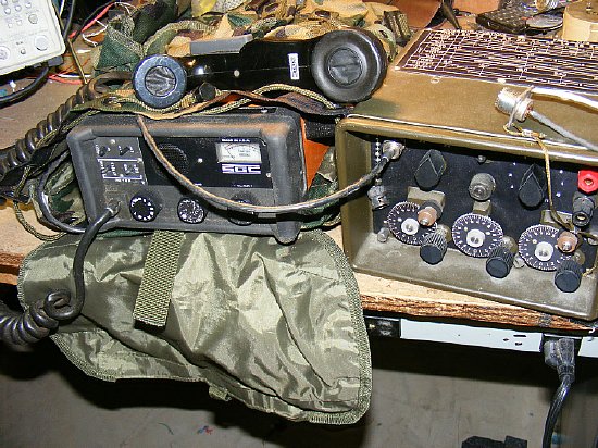
A possible use for this tuner would be to pair it up with the SGC-715.