Low Pass Filter Component Calculations and Construction the easy way.
The main purpose of this page is to get the builder to use the tabulated data in the ARRL Handbook.
Click here to Skip the intro and go to some actual construction.
This
saga started while I was preparing for Field Day 2017 and was looking
at a QRP rig the EMTECH NW-80. Several years ago I did a product review
for Wayne Green. The set was constructed from a kit and worked fine but
the 2nd harmonic in the 40 meter band was only 10-15 dB down. So trying
to improve on the 2nd harmonic level led me down this "Filter"
path.
Question: Why is it that one project leads you to another project which in turn leads you to another?

"73 Magazine" May 2000 page 38
The review was actually on the 40 meter version.
Typical Transmatch design by W1FB.
A simple solution to my 2nd harmonic problem is to use a antenna tuner for additonal reduction by 15-20 db. But I wanted at least 30db reduction with the set operating without a tuner.
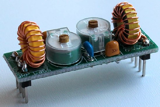
During my research I ran across QRP Lab's site and their miniature filter kits. QRP Lab filters are"Band Pass" and after I constructed one of their kits and made adjustments it met all specifications including low "insertion" loss. However I was more interested in a Low Pass Filter and at the same time I was concerned about the power handling capability of the QRP Lab filter. The QRP Labs filters are reasonably priced at $4.90 and will improve the front end of any single band receiver that does not have an adequate front end. Perfect for the typical home brew or kit receiver.
https://www.qrp-labs.com/
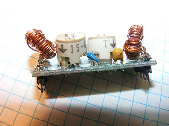
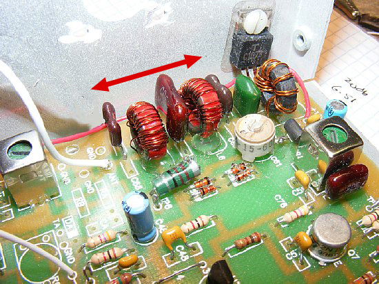
The QRP Lab kit is designed as a Front End Filter for a receiver to suppress signals below and above the operating frequency i.e., a bandpass filter. The kit is unique as you can adjust capacitors to peak the pass band however the toroid coils are very small and do not really lend them selves to winding adjustment on the lower bands such as 80 meters. I was concerned about the use of the power capability of the filter in a QRP transmitter so I substituted ceramic capacitors in place of the plastic capacitors. The ceramic cap installation is shown above.
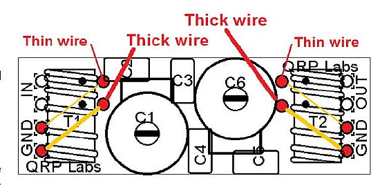
The boards are quite small and designed to be tucked into a receiver. Installing the toroid coils leads can be some what confusing. Price for the kit is $4.90. Note that the kit is shipped from Japan so it may take a while for delivery
https://www.qrp-labs.com/images/bpfkit/bpf.pdf
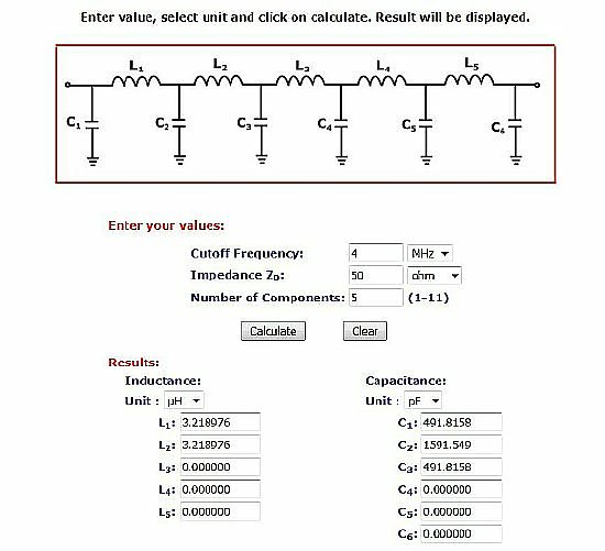
Designing
filters can be pretty mathy but I found a filter calculator at the Calculator
Edge Site:
http://www.calculatoredge.com/electronics/ch%20pi%20low%20pass.htm
In addition
the AADE filter design software can be downloaded from W1HUE's site. The
AADE software is fun and offers various options including performance
graphs and is a great "What If" device.
 http://w1hue.org/filter.html
Actual DIY construction of a low pass filter.
Problem: The filter calculators (links shown above) are great and design a perfect filter But the computed capacitors values are odd ball values and will require careful padding and manipulation of various values of capacitance to arrive at the values determined by the calculators. .
.
So if all else fails look in the ARRL Handbook
ARRL
Handbook. Copyright ARRL.
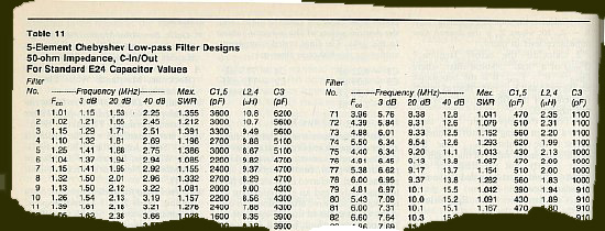
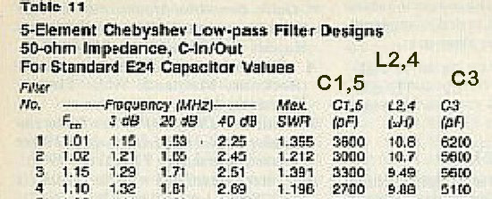
In
a 1991 Handbook in Section 2 I found a tabulated table for a 5 element
Chebyshev filter that uses "Standard" capacitor values. That
would make construction of a filter a lot simpler as the capacitor values
would be easy to duplicate. Silver Mica capacities would be used in any
case as they exhibit better tolerances and are readily available on ePay
and Mouser etc.
A full page photo is presented later down below.
ARRL
Handbook, copyright ARRL.
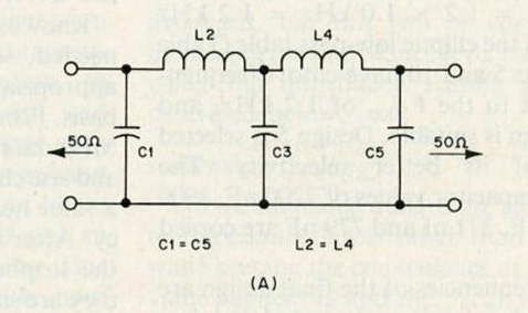
NOTE:
C1 and C5 are equal values. L2 and L4 are equal values.
ARRL
Handbook, copyright ARRL.
The
tabulated data provides standard values for C1,C5,C3. Note that C1 and
5 are equal and of the same value. C3 is a higher value. In addiction
the inductors L2 and L4 are of the same value. When using standard value
capacitors an exact match is not obtained and that is the reason for the
"Max SWR" column - but at these low frequencies loss will be
at a minimum. Hams worry too much about SWR.
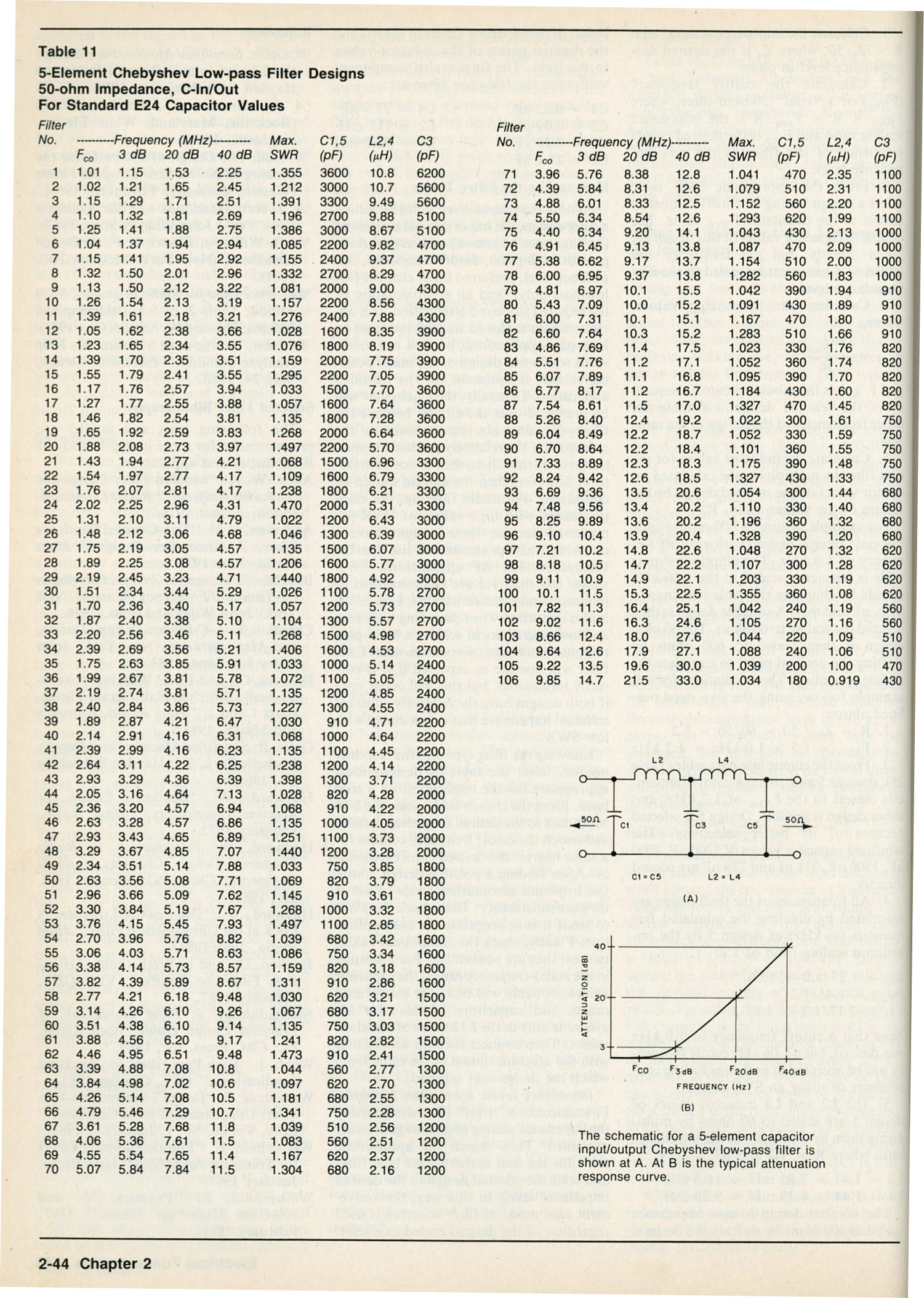
Copyright
ARRL. 1991 Handbook page 2-44.
CLICK
to enlarge.
Copyright k4che
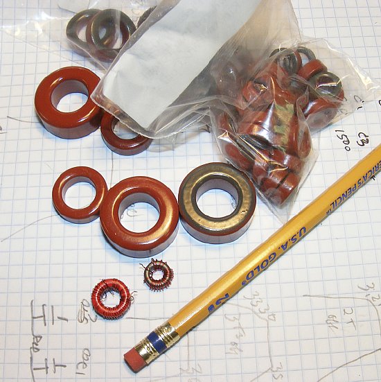
20 to 30 turns of wire on a toroid core will satisfy the inductance requirement of L2 and L4. It's not Rocket Science and each coil should take about 10 minutes to wind. You can walk on the wild side and wind a coil.
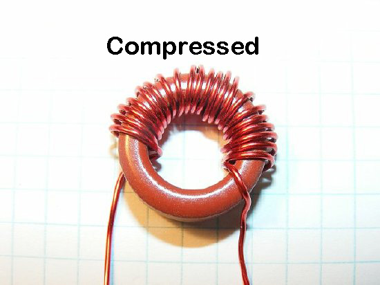
Sample coil. Measured inductance Compressed value = 3.5uH
The coils can be adjusted to vary the inductance. Compressed turns will increase the value. Expanded reduces the value.
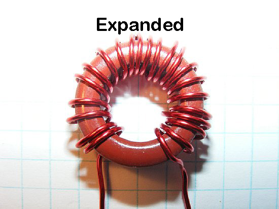
Sample coil. Expanded inductance value = 2.8uH
Bench test on a T50-2 core. By compressing and expanding the windings the total inductance can be varied all most 20 percent.
Q.
Where do I purchase the cores?
Ans. There
are boo-coo suppliers - -lately I have been using Kits and Parts.com.
Link below
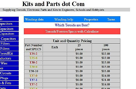
Kits
and Parts dot Com has a large selection and you can purchase in small
quantities. Type 2 material is suitable for the lower HF bands. A "T-37-2"
core is approximately .37(point 37) inches in diameter. A "T-50-2"
is a half an inch (.5) in diameter etc.
http://www.kitsandparts.com/toroids.php
Q.
How many turns do I wind on the core.
Ans.
Depends on the inductance. But visit the link below and use their "Turns
Calculator"
Here
is the link for a T-37-2 core.
http://toroids.info/T37-2.php
Ans. Use the link above and scroll to the bottom for a "Turns Calculator".
Q. What wire size?
Ans. Try #24 or #26.
Q. The ARRL tablulated data calls for a capicator 1600. All I have is a 1400pf. Will that work?
Ans. Use the 1400 pf and I doubt if you can tell the difference. However you should pad a 200 pf across the 1600 for best results.
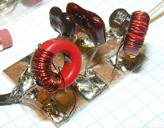
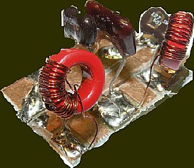
K4CHE test board 80 Meter
Low Pass Filter. 50 ohm coax used for input and output
Its
easier if you *"Breadboard" the circuit first Note the amount
of space available on the red cores to expand and compress the windings.
* Breadboard is a term used years ago when you would go to the
hardware store - put a dime down on the counter and purchases a nice smooth
wood breadboard and use it as a base for your project. The original purpose
of a breadboard was to roll bread dough with a roller pin? Google Roller
Pin.

Typical Chebyshev filter designed by software. Not ARRL. My ARRL plot for 30 db was approximately 7 Mc.
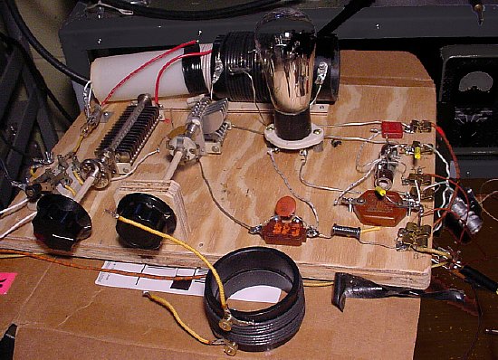
Breadboard Construction. 1929 Hartley Oscillator by k4che
Here is photo of a 1929 Hartley Oscillator that was "Breadboarded" on a piece of plywood. Its easy to change locations or values of components when they are mounted to the board with simple wood screws. This breadboard rig was used in the Antique Wireless Association Bruce Kelly event which requires transmitters of 1929 design or earlier. Lot of whoops and chrips. Enough of this folderol.
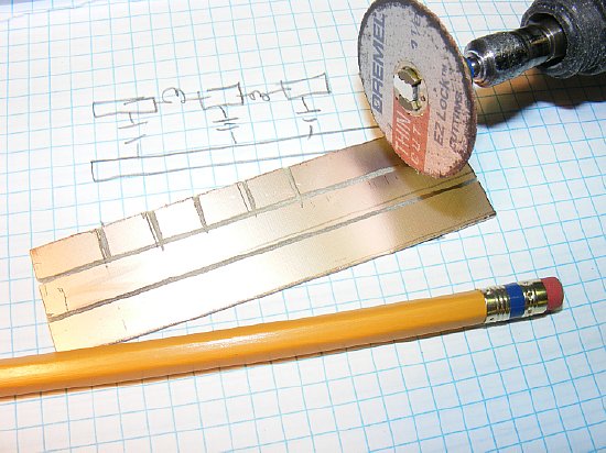
Convenient solder "Islands" can be constructed using a Dremel tool and single sided circuit printed circuit board. WEAR safety goggles.
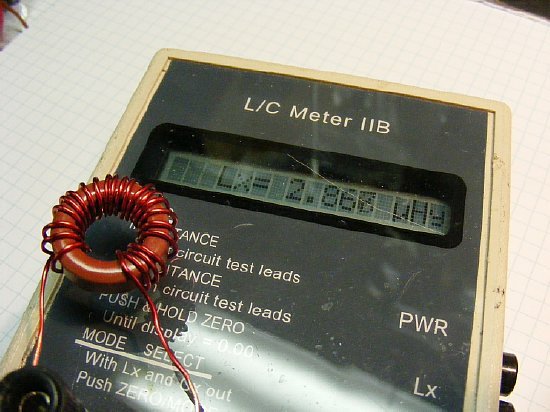
A L/C meter comes in handy but not absolutely necessary if the "Turns Calculator" is utilized.
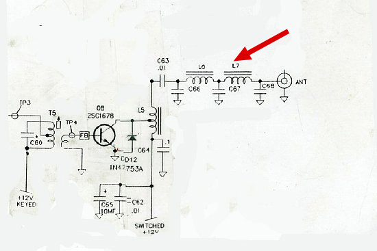
Finished
Low Pass Filter installation. k4che
The
finished filter components installed on the QRP NW-80 QRP board.
Tuning: The easiest way is to just tune for maximum forward power, minute changes may be made on 80 meters by expanded or compressing the turns on the cores for best power. The tuning of the cores become more effective on the higher frequencies.
Ready
for Field Day and on to the next project.
The ARRL Field Day is a great event. Here is a link to the K4CHE operations during 2016.