
The Mission: Duplicate* the aircraft radio position equipment rack utilized by the B-26. Use the Smithsonian Display Aircraft "Flak Bait" as a model.
*Using basic hand tools and common materials.
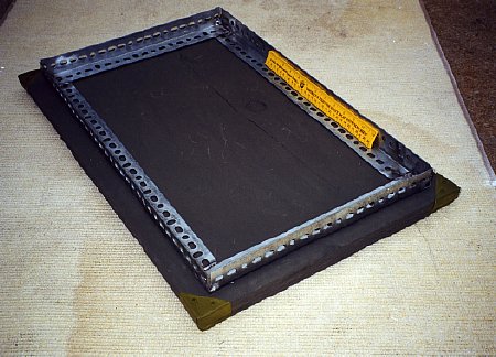
Steel
"framing angle" makes a good start and a sturdy bottom platform/foundation
and you can easily connect it without welding. My bottom frame
measures 24 by 15 outside to outside
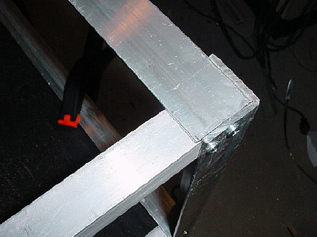
Standard aluminum
angle 1 inch X 1 inch by .125 was utilized for the main vertical posts
and shelf supports. Save money and order a supply of angle aluminum on
line it will be cheaper, a lot cheaper than going to your local building
supply store. I prefer 6063 type angle which has square corners inside
and outside. Zinc chromate paint was applied to the main bottom frame.
The height of my "present" rack is 44 inches which is a little shorter than scale but was necessary as I had to modify it later for my operations. See later pages.
I
do not have and I do not have access to the original drawings of the radio
installations/avionics racks in the B-26. There have been individuals
that claim they have blue prints etc. and that they are constructing the
racks and the actual radio position but so far after several years nothing
as developed.
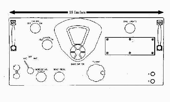
I used the "Width" of the BC-348 which is 18 inches and scaled my rack accordingly and arrived at the 24 inch width.
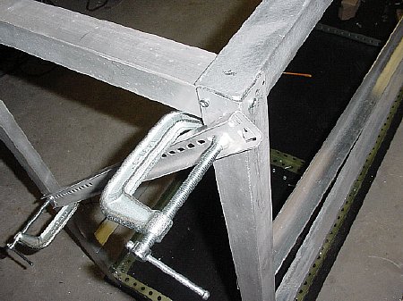
"C" clamps come in handy during initial construction. The cross bracket shown is not part of the structure as it was used to hold the rack in a "square" position while drilling holes.
Be
sure and Visit http://aafradio.org/
and read Mike's description of some of his rack construction and layout
of his "Flight Deck".
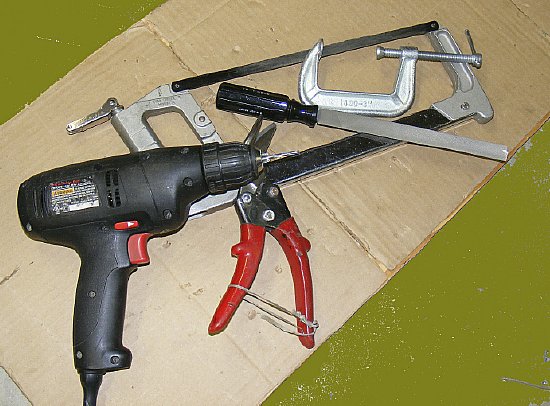
Hand tools required for the project.
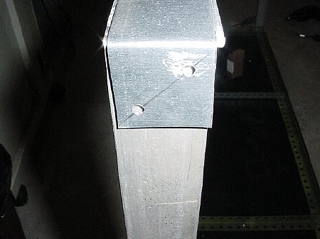
A drilling template is used for drilling the same hole pattern over and over.
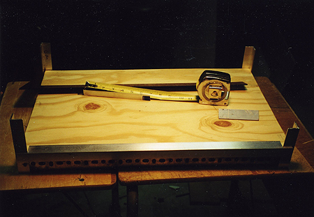
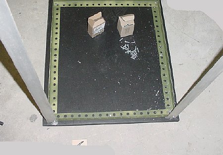
Short posts are temporally mounted to the bottom base frame for determining the dimensions of the the plywood shelves. Once you have decided then you can either cut your own shelves or have your local home supply store cut your plywood when you make your purchase.
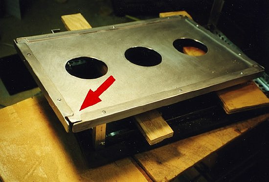
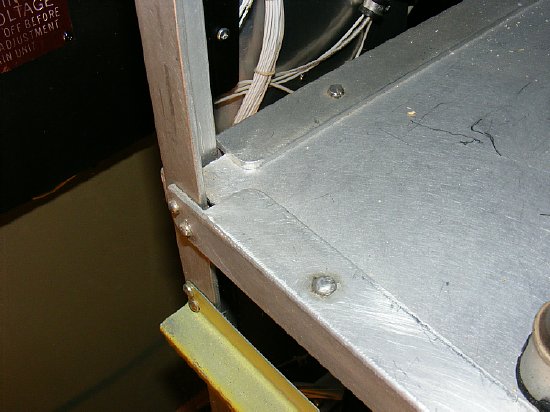
The edge angles have notches cut to enable sliding the shelves up and down the corner posts to arrive at the desired position and makes it easy to change later.
The shelves can be moved up and down the corner posts for proper position of equipment and for maintenance. Notches were cut into the ankle aluminum and edges rounded with a file.
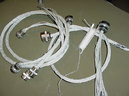
Take a
break from construction and start on your cables. A "bobbin"
comes in handy to hold and distribute the lacing. The Collins Quality
Standards Manual contains detail on lacing. Make the cables long enough
for any contingency. I changed my mind about the control
head mounting 3 times during construction which required adding an extension
to several cables. See later pages for major changes in the overall "Flak
Bait"construction.
You can download the Collins Manual pdf file from the K4OZY Collins Repository.
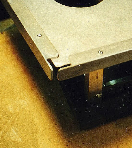
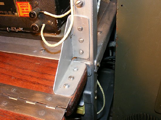
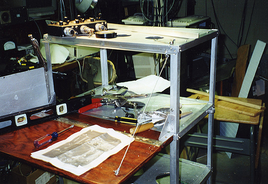
Just for fun most of the Phillips head hardware was filed flat and capped with solder for that rivet look. The top of the rack is shown. The cable supports the fold up desk. Note that the metal has been "subdued" and corners rounded somewhat to resemble the original legs bent from aluminum sheet.
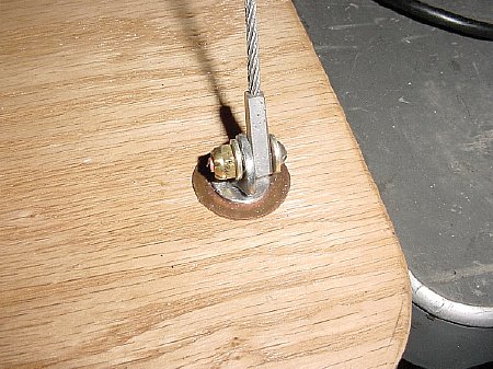
Desk cable fixture. I utilized a cable "end" smashed it with a hammer and filed and shaped it with a hand file. The assembly that is mounted to the plywood desk is made out of a thumb screw filed flat. Shown below.
5/8 inch plywood was utilized for the desk. The narrow support piece was 23 3/4 wide by 3 1/2 width. The main writing surface measures 23 3/4 by 11 1/2.
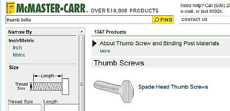
McMaster-Carr has a large selection of hardware.
http://www.mcmaster.com/#
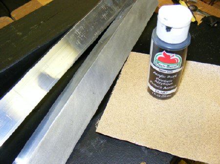
The brand new aluminum angle can be subdued and "aged" slightly by using a small amount of black acrylic paint, "wipe paint on, wipe paint off" Sand it with fine grain paper first. Compare the original new angle on the left and the subdued angle on the right. Sharp corners can be rounded to simulate the original bends.
Top section. Some filing required to join the pieces.
The mounting screws for the desk were left alone for future maintenance to allow easy removal. Note the placement of the piano hinge. The brackets can be bent in a vise.
Construction of the "Flak Bait" radio rack would be incomplete without the unique folding desk it contributes to the overall personality of the project.
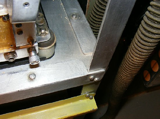
I don't have any idea what the zinc chromate cross bracket below the shelf is used for but it was on the original at the Smithsonian. Zinc chromate primer can be purchased from your local Marine store or on line from an Aviation Supply House.
Shelves
are easy to move up and down to get level. The shelf is extremely strong
as it is plywood covered with aluminum.

Tip: Economy aluminum sheeting for covering the top of the shelves can be purchased at your home supply store in rolls. Ask for a roll of "flashing" aluminum. Comes in various widths and some widths have an adhesive backing.
Now I am starting to think about the equipment control heads and where they will be placed. On the aircraft they were positioned in the cockpit.
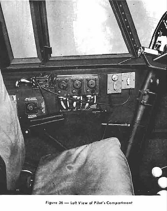
Cockpit mounted controls.
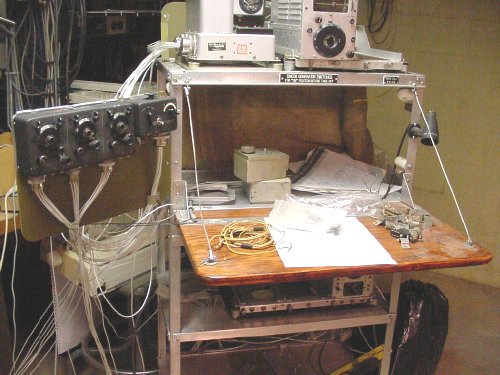
A decision was made to mount the control heads on a hinged panel. Sort of looks like a training module you would see in a Field Training Detachment. The hinge pin can be removed and the control panel stored for transport.
The
hinged panel can be folded for ease of movement of the rack. My original
concept was to build the rack for display at hamfest and military rallies
but that concept changed later on as the "Flak Bait" project
grew larger in concept and size. See later pages.
Like all projects the initial project eventually spawns other projects which spawn others etc.
| Ask my wife she will explain it to you. |
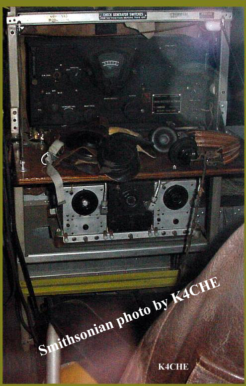
The "Flak Bait" rack in the Smithsonian.
%20copy.jpg)
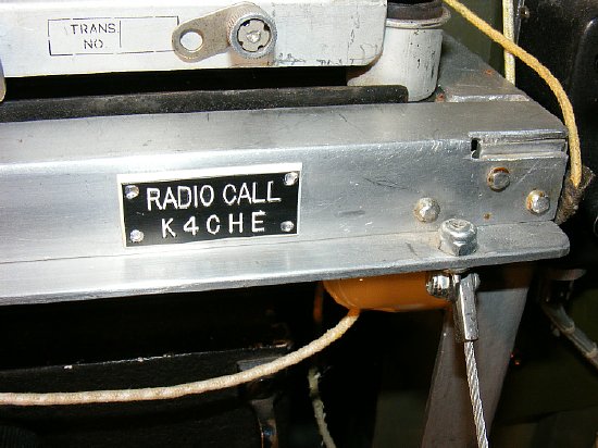
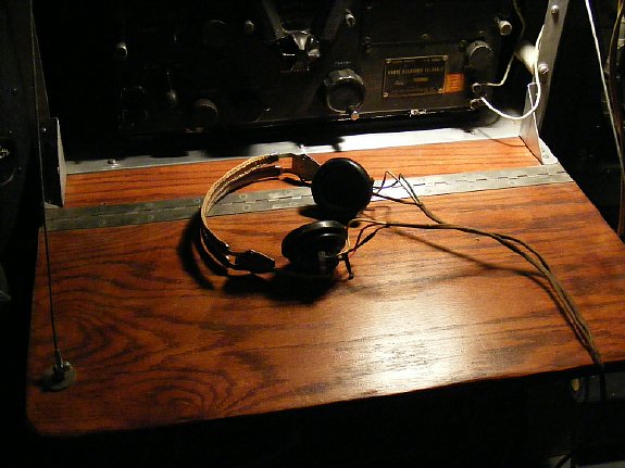
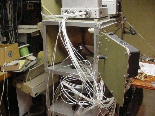
K4CHE close up. Mission Accomplished? But this is just the beginning as the project grows.
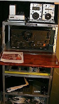
K4CHE fabricated "Flak Bait" radio rack and desk with a partial installation of the equipment. The saga continues.