
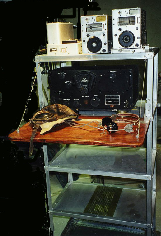
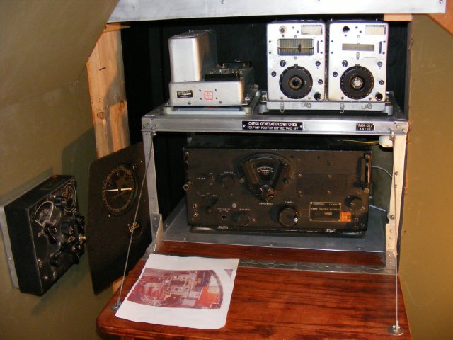
The basic "Flak Bait" rack was finished but . . . But now where should I place the rack and it equipment in my "Operations Center".
I wasn't happy with any of the control head locations that I tried and needed an alternate mounting scheme.
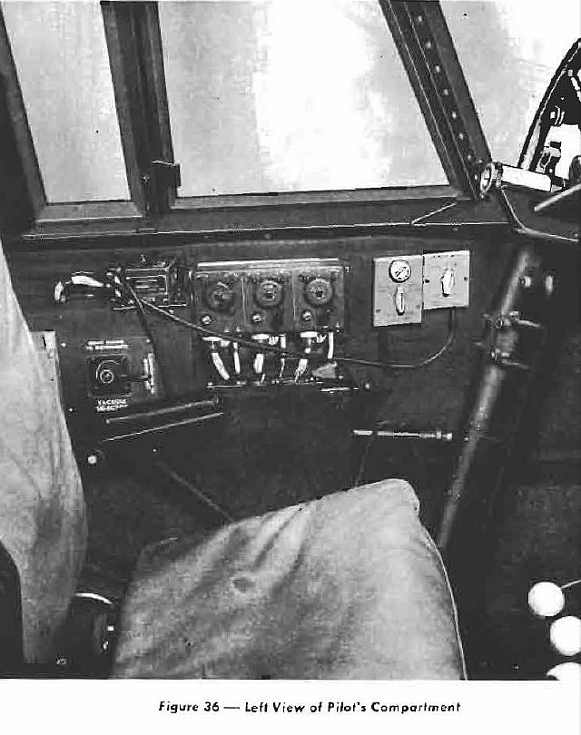
The control heads for the Command Sets on the B-26 were mounted in the cockpit.
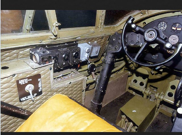
Cockpit photo of a B-26 under restoration.
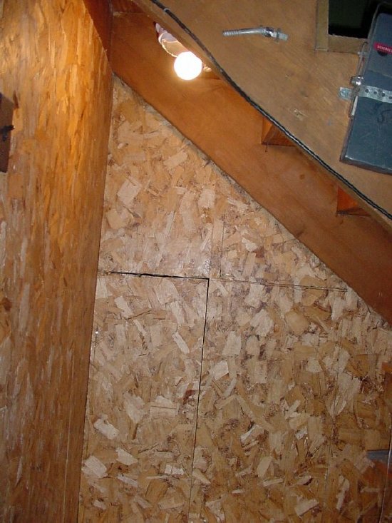
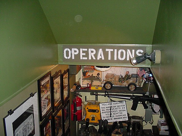
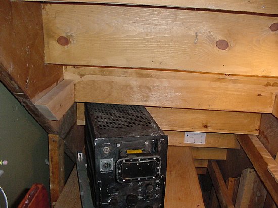
There was a "spot" available under the stairs of the entrance to the "Operations Center"
Improvise, Adapt and Overcome ?
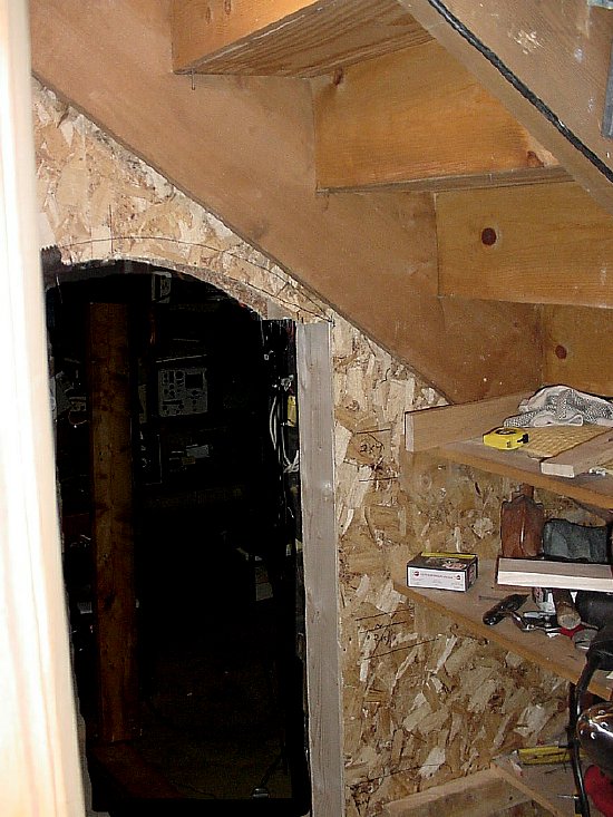
But the Rack did not fit into the under stair space. "What is that sawing sound?"
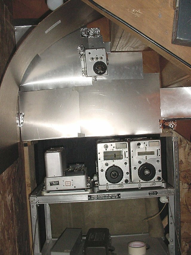
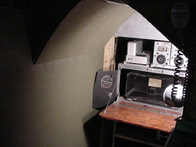
After a little sawing the rack fits but what to do with the stairs that look like stairs? Maybe try a curved ceiling and cover the interior with sheet aluminum to alter the overall appearance.
A basic construction plan developed and a decision was made to remove the control head panel from the "Flak Bait" rack and mount in the interior space under the stairs.
Thus the beginning of travel onto the "Slippery Slope" where multiple project events will eventually transpire - - all carefully linked and and the process expands and goes back and forth.
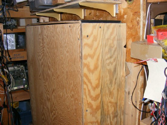
A rear "box"enclosure was constructed to cover the rear of the"Flak Bait" rack as it extended into the "Parts Room".
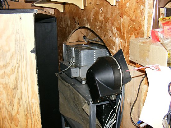
The rear box enclosure could be removed for equipment maintenance as well as installation of a hidden speaker, main power wiring etc. The interior of the enclosure was painted flat black.
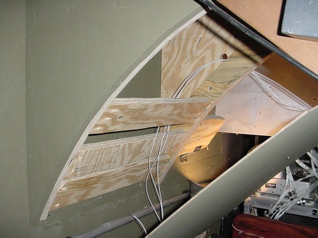
The
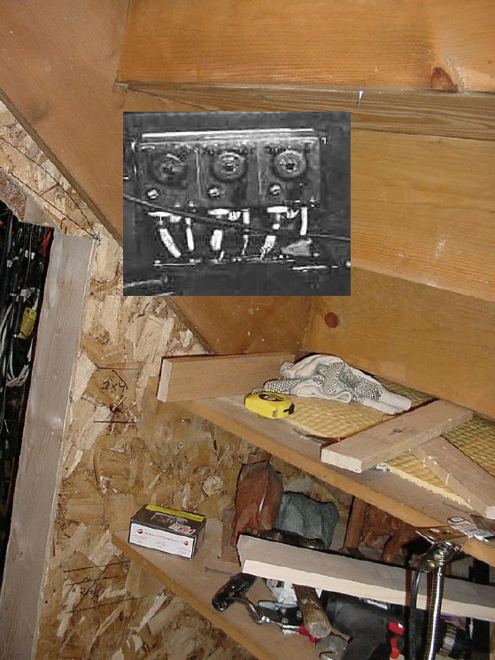
ceiling takes shape using 1/2 plywood "formers" - - the ceiling
design allows for easy removal for ease of wiring and to make the inevitable
changes that would take place.
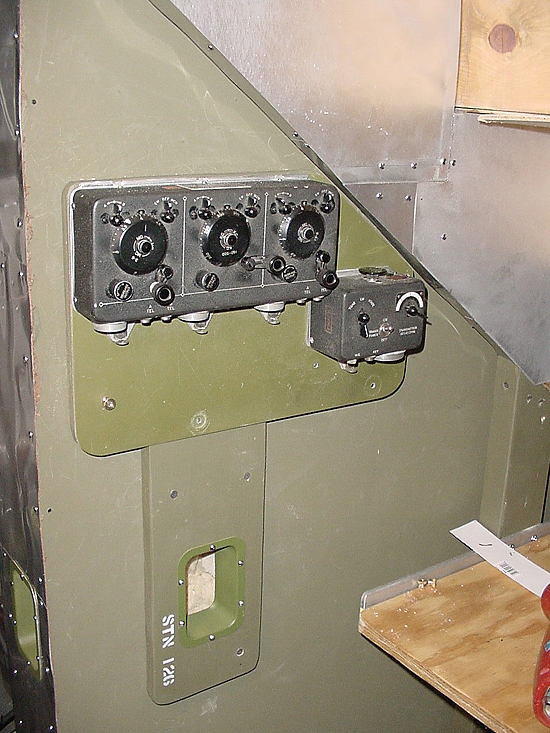
Finally, a location for the control heads. "Station 126" is the perfect location for the control head panel that was previously attached on the left side of the rack. Progress. And an idea for a Navigation table has spawned. The project expands.
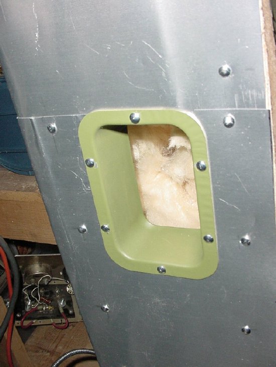
The control cables will exit through the wall via a fixture found at "Lowe's". That is if I can get all that fiberglass insulation out of the way.
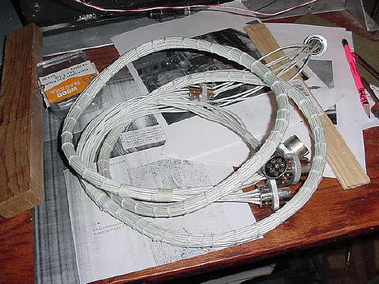
Speaking of wiring, I had to redo a couple of cables to accommodate the new length need for the control head location. Plan your cables carefully.
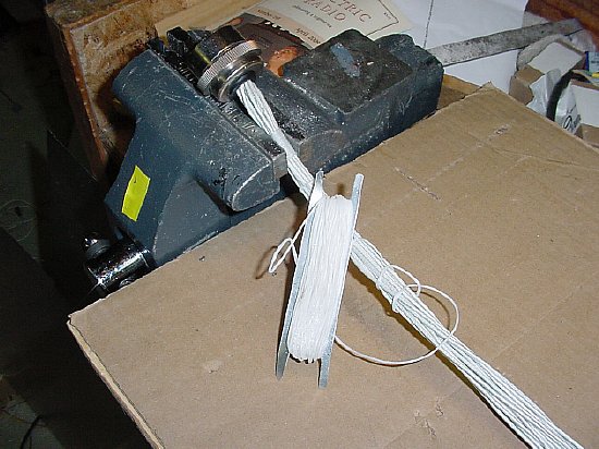
A bobbin to hold the cable lace material comes in handy.
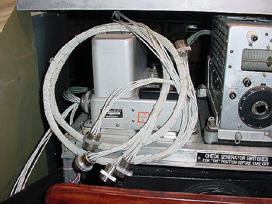
Longer cables are now finished for the new control head location.
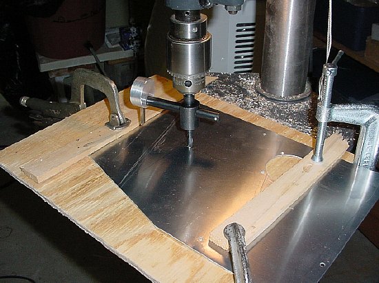
My control head location changed and now I had room to the left of the rack to mount the Aux panel shown in the photo below. I deviated from my "hand tools" rule and used a drill press to hold the rotating hole cutter for obvious safety reasons. The hole cutter tool shown was purchased from Sears. A Dangerous tool, uses C clamps to hold the metal.
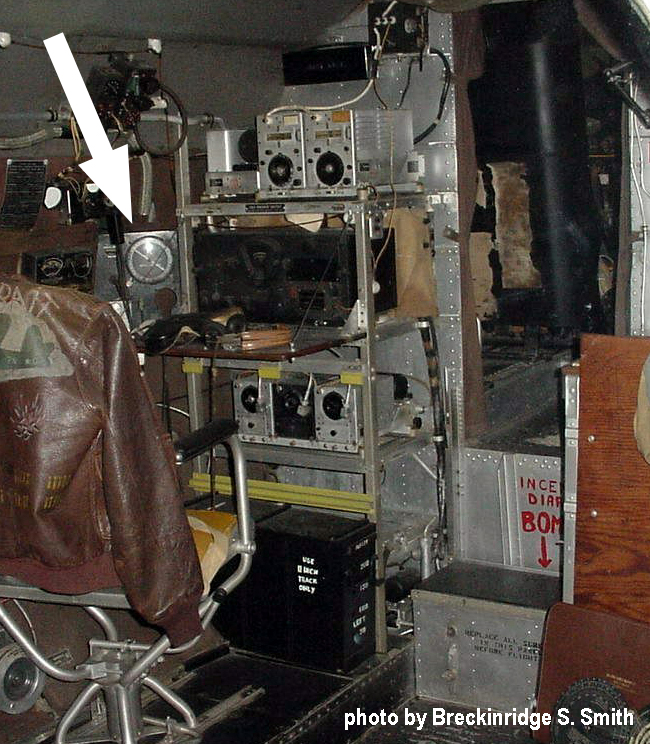
White arrow points to what I will call the "Aux" panel.
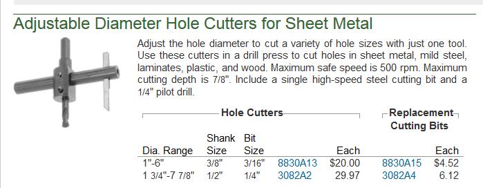
McMaster-Carr also lists a "Hole Cutter" in their catalog.
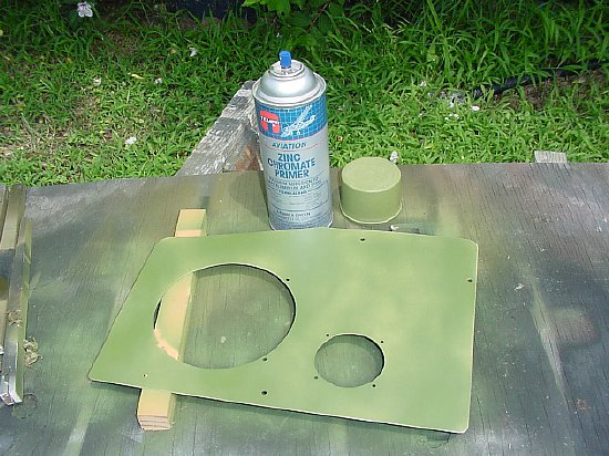
Zinc
chromate primer makes a good undercoat for black wrinkle. The paint is
available from Aircraft and Marine suppliers.
"I love the smell of Zinc Chromate in the morning."
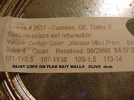
Speaking of paint you can take the above formula for Olive Drab paint to "Lowe's" or take in your own painted metal or wood sample and let them "shoot it" with their optical sample gun and make up a batch for you.

Zinc chromate for the walls.
I
liked the Zinc Chromate color and used it for the walls of the descending
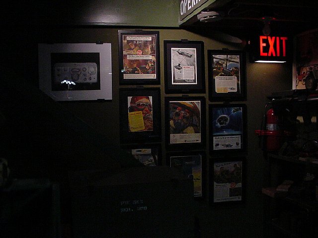
stairs entrance to my "Operations Center". When I was a USAF
Navigator prior to Pilot Training I always enjoyed crawling around inside
some of the USAF aircraft "Crawl Spaces" and "Hell Holes"
because of the zinc chromate color. If you were smart you always took
an Oxygen bottle. Maybe the color on the wall is good therapy.

My
cargo sticker used in Vietnam to mark my loads.
Operations Entrance
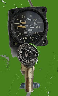
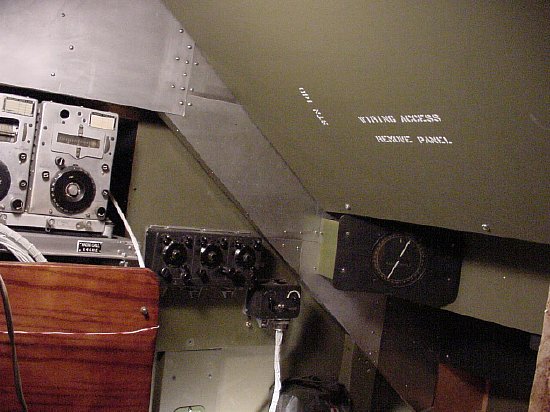
The "Aux Panel" with the ID-81 is installed and needs to be populated with additional boxes. I popped an AC meter in the blank hole but I think a A-9 oxygen regulator needs to be in that space.
Epay Photo
A-9 Oxygen Regulator
The C-4/ARN-7 ADF control head was temporarily mounted to the port wall to check ease of operation and to measure control cable lengths.
The ARN-7 project is another story. Thank you Mike for the "proper" C-4 control head.
NOTE that the "Aux Panel" to the left of the BC-348 is mounted on a hinge to allow the panel to fold inward for ease of movement and maintenance of the rack.
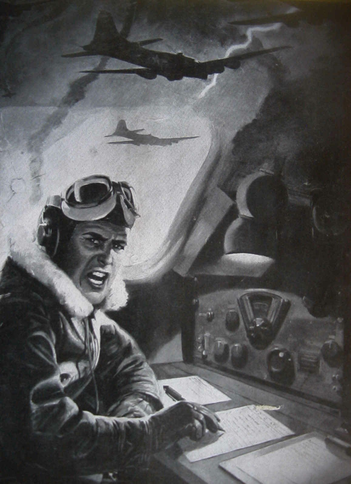 Speaking
of the BC-348, click to enlarge my favorite
Speaking
of the BC-348, click to enlarge my favorite BC-348 B-17 photo. Source is unknown.
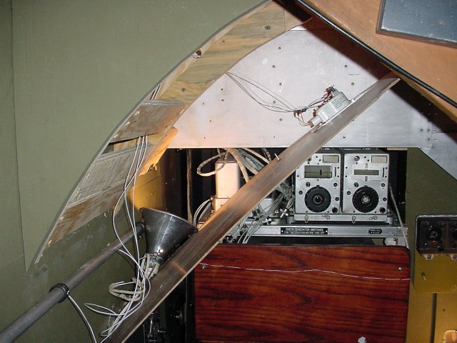
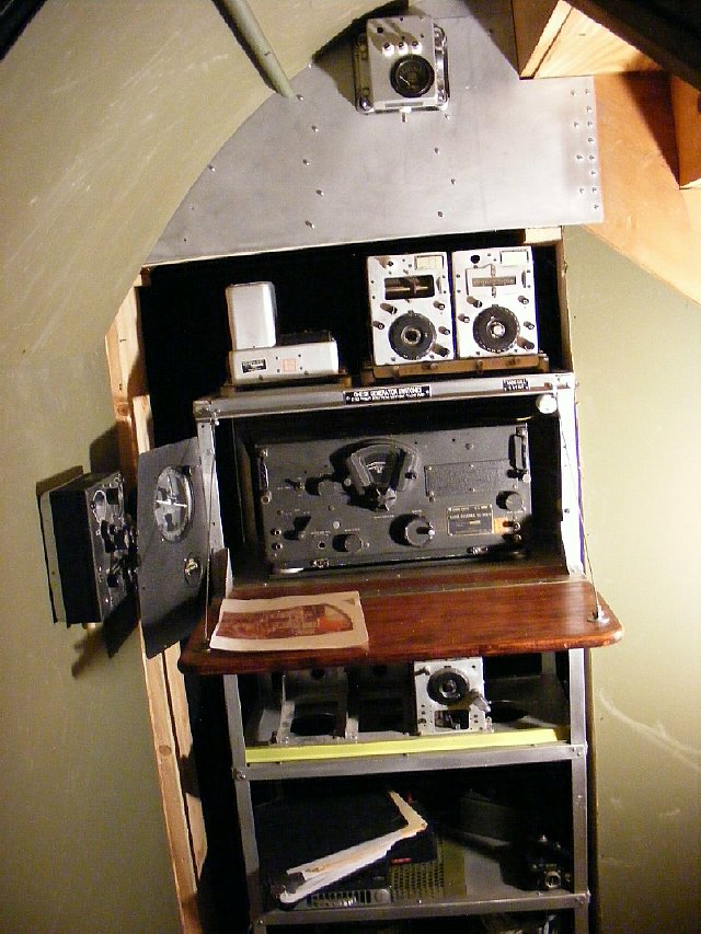
The ceiling was lowered and a aircraft light fixture was installed. Note that rivets were installed on the aluminum sheet on the bulkhead. Control heads are now mounted down to the right. The conduit on the port wall will be utilized for power cables.
Domed "screw nails" were used for the rivets.
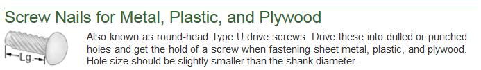
Portions of the conduit installation on the B-26 "Flak Bait" position were modeled. DC and 400 cycle AC Power for the project will enter through the wall using the small handy box for initial distribution and to feed the radio position. A cable has been prepared for the ARN-7 control and is waiting for installation.
"I
love it when a plan comes together."
The control heads are mounted and the "Stairs Look" has been changed with a removable false ceiling and I was happy that I found a place for my extra I-82-A and thus another project spawns from this project the "Navigators Position"-- more on that later. This confirms the "slippery slope" theorem. The I-82-A will be wired in parallel with the Master Indicator mounted on the Aux Panel. Note that the "Flak Bait Rack" table has been folded to the stowed position.
. . . and the Navigation Position has started, first will the APN-9 fit?