 |
K4CHE GO-9 HF/MF Transmitter Project: HIGH VOLTAGE SUPPLY |
 |
A Saga of sorts. My construction techniques for a High Voltage Supply for the GO-9 Transmitter.
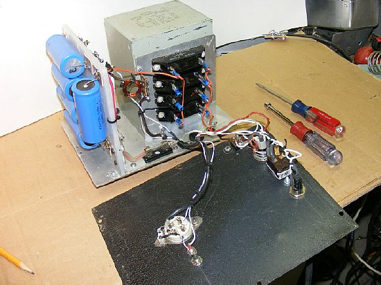
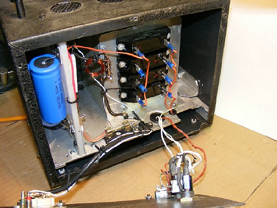
I had constructed most of the power components for my GO-9 Rectifier on flat trays for ease of maintenance and to allow easy insertion and removal from the main chassis of the Rectifier. The previous owner of the Rectifier assembly had stripped out most of the components so a major power supply and control constructing project was necessary. I continued the tray construction technique with the the High Voltage Supply.
.jpg)
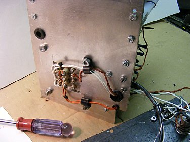
A simple discharge stick. Use wood, high voltage cable, a good quality alligator clip and a simple tip from #12 wire.
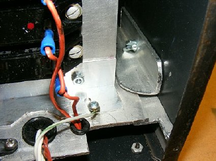
The high voltage tray mounts inside a "Bud" cabinet and is help by clamps fabricated from 3/4 inch right angle aluminum. A single thumb screw and bolt hold each clamp in place.
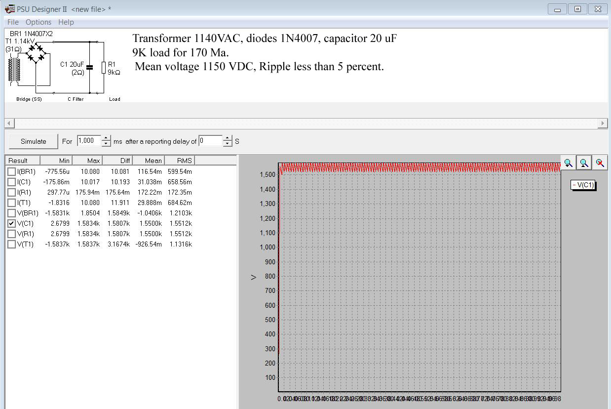
My HV supply utilizes
a standard bridge configuration and a capacitor input filter.
 Click to Enlarge
" Power
Supply Designer" simulation came right out on the money with bench
testing after construction. This is easy to use software available at
no cost and is perfect when you want to try out different power supply
components and ask "What If"? In this case my transformer
output was 1140VAC, a bridge rectifier, a capacitor input filter of 20
uF and my load simulation for 170 Ma was 9000 ohms. The diodes that were
used for the simulation were 1N4007X2. The standard maximum ripple voltage
for years for a "code or CW transmitter" has been 5 percent.
We were at .045 on the ripple - - close enough for government work and
this allowed us to keep the parts count down (no choke etc.) in the high
voltage supply and make everything fit. You can add a choke prior to
the capicator to reduce the ripple slightly but be prepared for a drop
of 400 to 500 volts. Based on the above "simulation" I pressed
on with construction with just the capicator input filter.
Power Supply Designer Program is available at the "Duncan Amp" pages. "PSU Designer II is designed to help you with the design of simple linear (unregulated) mains power supplies, as often found in tube amplifiers." The simulation software also includes Tube type rectifiers such as a 5R4, 5Y3 etc.
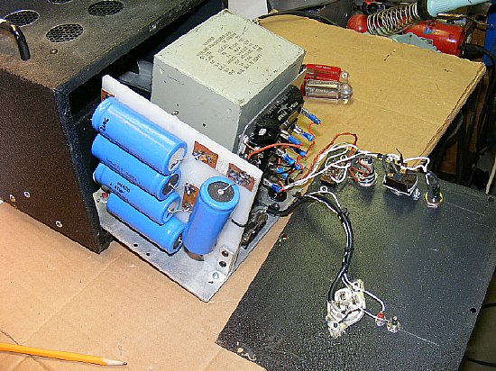
The
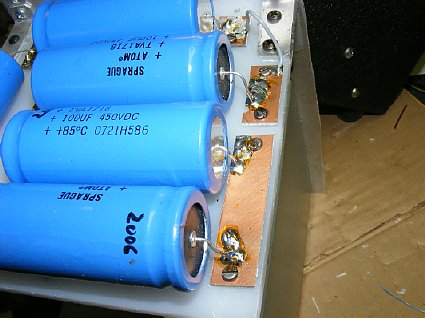
tray slides out for easy maintenance. The 100uF caps are shown soldered
to the small "islands" of copper clad PC board which are attached
to the lexan. The 450 volt capacitors are in series and are 100 uF each.
A total of 5 capacitors resulted in total of 20uF.
Since I needed
a bleeder resistor I choose to use 5- 20K power resistors which provided
voltage equalization for each capacitor. On smaller power supplies I often
omit equalization resistors when putting capacitors in series if the rated
voltage for the capacitor is not exceeded.
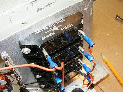
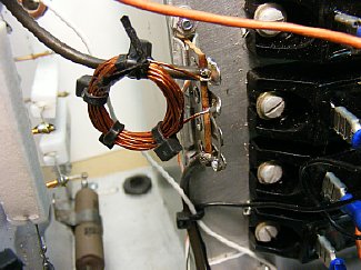
The Diode Bridge uses K2AW's famous diode blocks. Sadly to say they are no longer available from K2AW but a search on ePay for "high voltage diode block" or "high voltage diode" will provide you with other choices.
These diode blocks are pretty rugged, I did not use the traditional 10 ohm surge resistor in each output lead of the transformer prior to the diode blocks for surge protection.
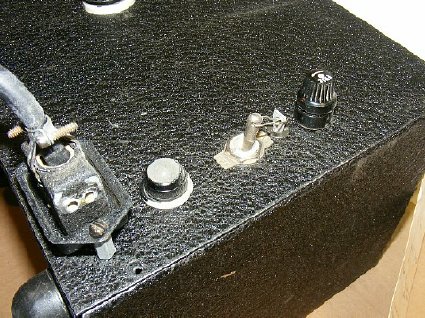
The master switch is safety wired to the "On" position as the GO-9 Rectifier Panel will provide control. Drill a hole in the bat handle of the switch to accommodate the "safety wire".
 Click to enlarge
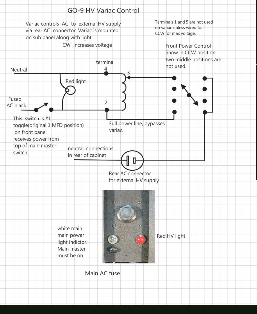
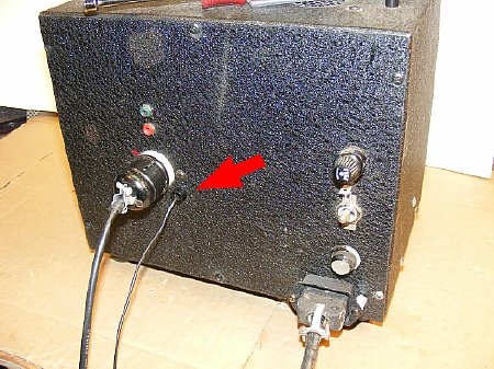
 A variac on the GO-9 rectifier panel provides control of the high voltage for adjustable transmitter power levels. The HV supply provides 1800 volts no load and 1550 volts when the transmitter is loaded to 175 Ma.
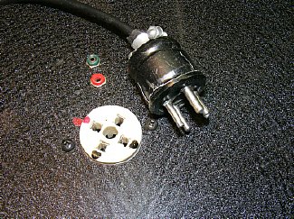
With my working voltage of 1550
VDC I used a ceramic socket and standard four pin plug.
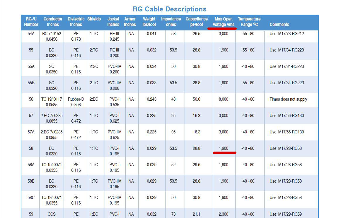
The cable is constructed from a good quality
RG-58. One of the pins is used for the HV and two of the other pins are
used for the ground (shield). The green and red tip jacks are used for
test metering. The green is for current via a meter shunt in the minus
lead and the red is for voltage via a 47K resistor tied into the last
bleeder resistor.
Good quality RG-58 is an excellent choice for the HV cable. Leave the shield intact for safety and for the ground.

 Click
to enlarge
Click
to enlarge
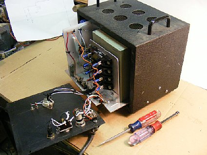
It all fits.
The mounting "islands" made of copper clad PC board mount to the lexan board using small screws.
"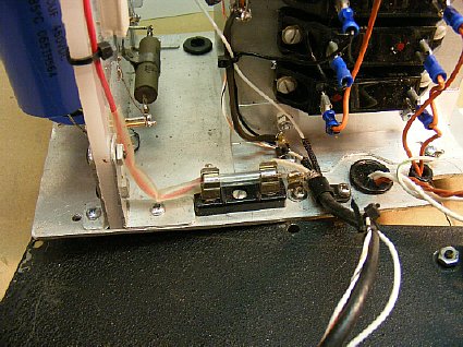
One
inch pieces of #12 wire extend through the lexan and serve as soldering
posts on the other side for the resistors. Note the fuse which is located
in the B plus output line. I use a 1/2 amp. The fuse is not "rated
for high voltage but when the B plus is accidentally shorted it will blow
and the link will vaporize. The fuse is installed to protect the diodes
blocks.
A small
meter shunt was installed in the minus side of the power supply to provide
external metering via a test jack on the front of the panel.
The tray is mounted on brackets in side the Bud case and the wiring on the bottom of the tray is well above the bottom of the case. Note the feed through grommets.
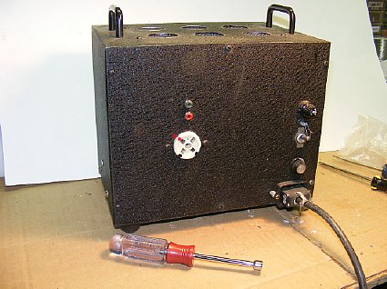
The "Bud" cabinet has a width of 10 inches, height is 8 inches and depth is 7. Handles were attached and 1 1/4 inches cooling holes were cut in the top. ePay is a good source of cabinets.
The
RG-58 shield is the B minus return and ground. An extra "safety"
ground wire was attached directly to the tray.
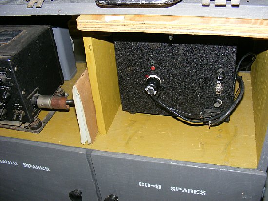
The small HV supply fits easily on my GO-9 accessory shelf. The white light below the switch is redundant as there is a "HV" ON light on the GO-9 Rectifier panel.