 |
RF Ammeter's |
 |
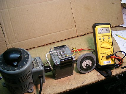
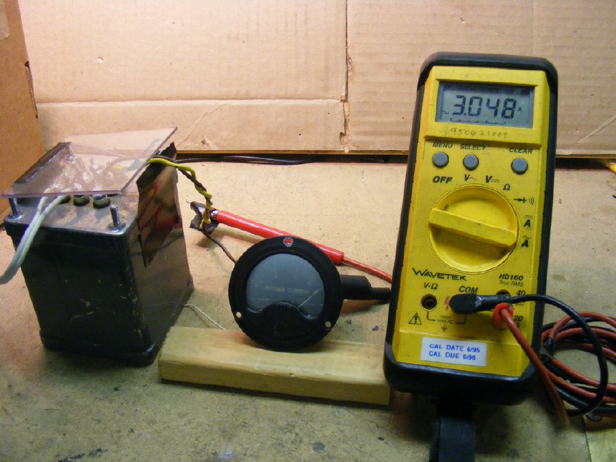
A
test jig for checking the calibration of a RF Ammeter. A variac feeding
a filament transformer. Thermocouple ammeter readings will vary slightly
when you change frequency but 60 cycle AC is fine for testing and calibration
for amateur radio use.
TIP: A variable DC supply can also
be used and for amateur radio purposes using DC will be close enough.
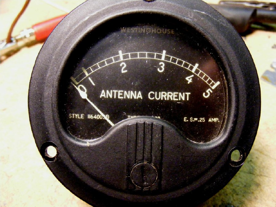
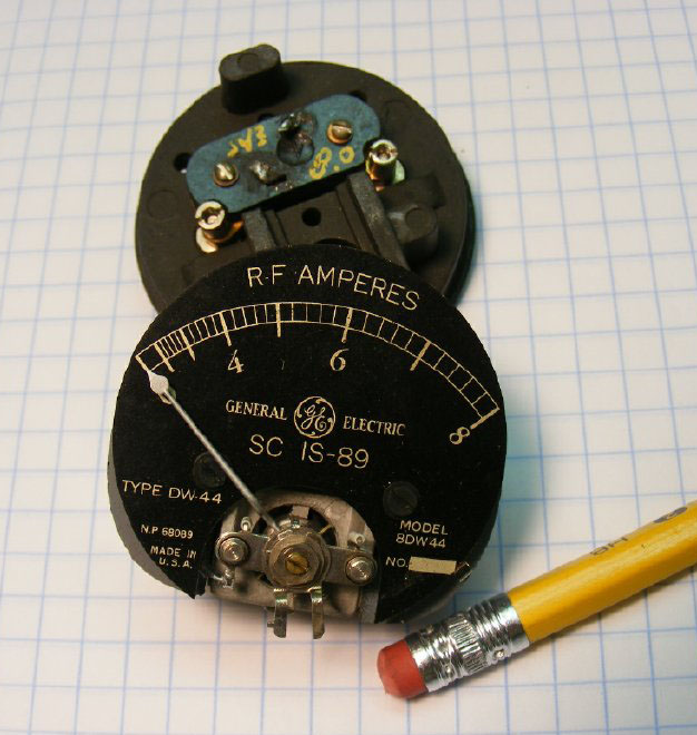
A
lot of the meters have the F.S. (full scale) value printed on the front
of the scale.
Tip: Initial evaluation of a
meter. A high current meter will have a measured resistance of a
couple of tenths of an ohm. A low current meter will measure several ohms.
Mystery
meter ? Resistance was around 2 ohms. Is it an actual 3 amp meter? After
testing it was determined to be a 3 amp meter.
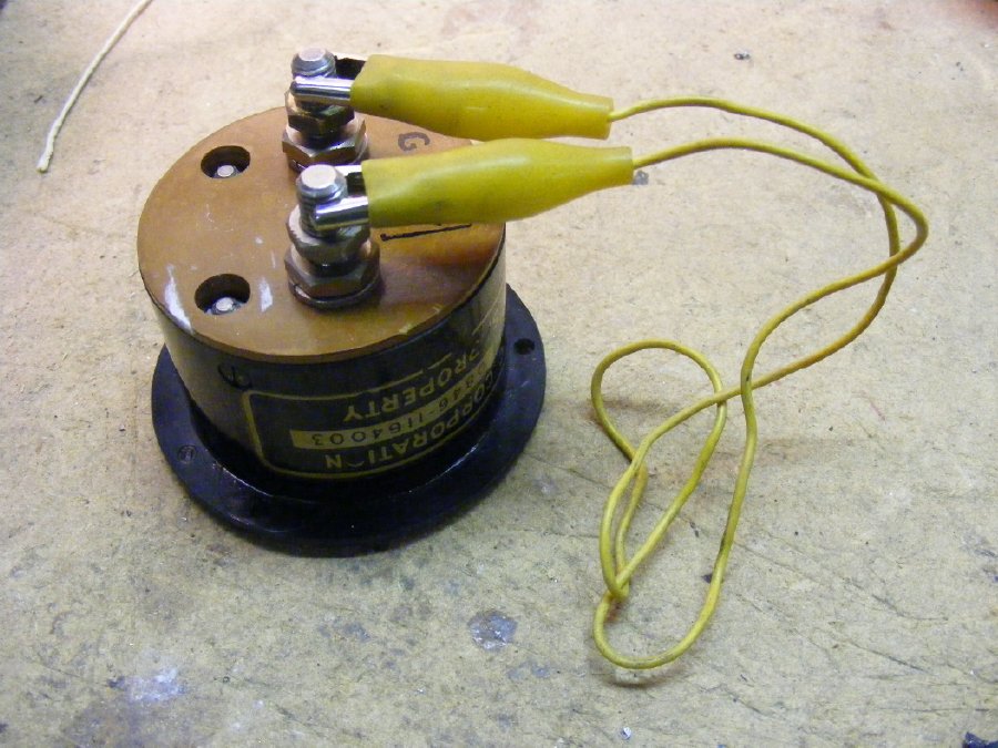
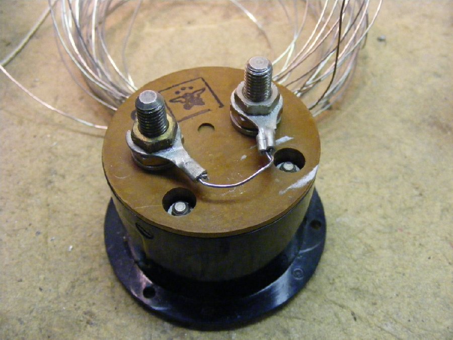
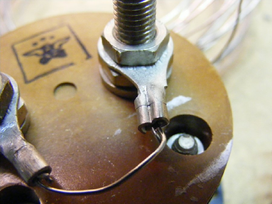
A
simple "clip lead" shunt during testing of the .25 amp meter
changed it into a 3 amp meter. Be careful when doing any testing, don't
let your shunt slip off resulting in high current going through the meter.
The
"clip lead" shunt used on a .25 amp meter resulted in a 3 amp
meter.
Resistance wire can be used to make a shunt for low value meters so that they may be utilized on high power transmitters.
One of
the problems with using "resistance wire" is that it is made
of nichrome type of material and it is all most impossible to solder.
Crimp any connections.
TIP: Look in your junk box for large wattage power resistor, find a donor and remove some "resistance" wire. Or just do a search on ePay for "resistance wire".
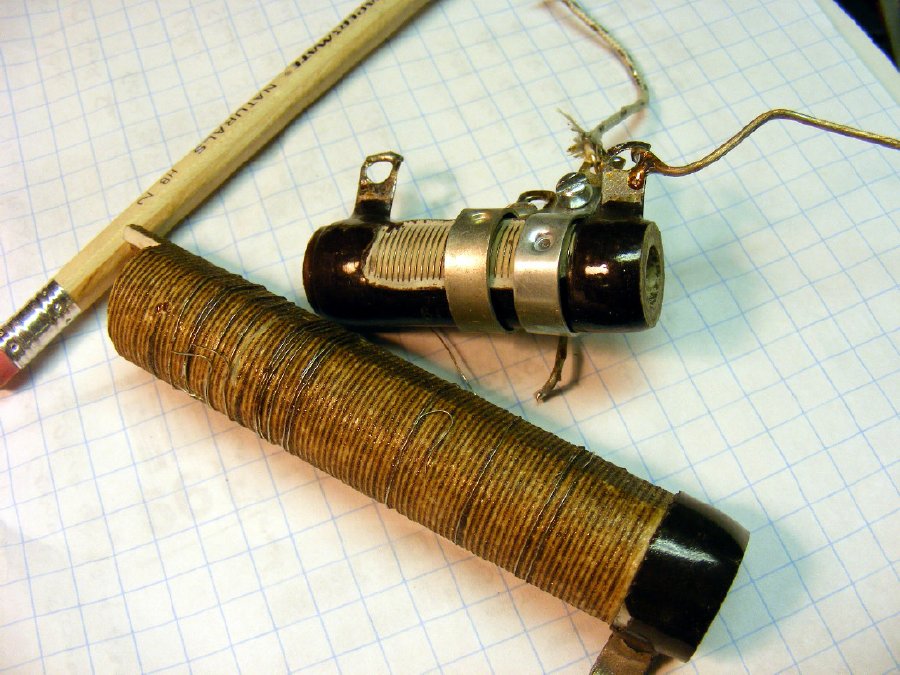
Junk
box resistance wire.
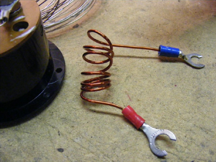
A simple shunt using plain copper wire turned the .25 Amp meter into a 10 amp meter.
This
meter has a bad thermocouple. In my opinion thermocouple ammeters were
born to fail. Clete WB2CPN suggests putting a switch to bypass the meter
when it is not being used to save the thermocouple.
TIP:
In a restoration project when you have a bad thermocouple use the basic
meter movement and an external current pickup. Throw the thermocouple
away.
TIP: Occasionally
you find find a meter that is all most impossible to disassemble. In this
case just remove the meter scale and put it on another meter and use an
external current pickup.
.JPG)
A decade resistance box
and your multimeter on the current position in series with a low current
supply will allow you to determine the full scale value of the RF Ammeter
basic movement. Be careful as most of the meter movements are in the 50
uA to 1 Ma range.
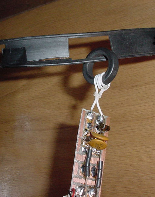
The copper clad board has groves cut by a Dremel tool.
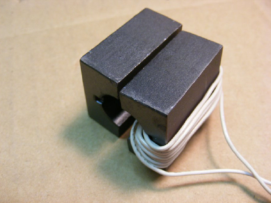
The ferrite core transformer splits and the RF line goes through the center.
TIP: Be sure and tape the two sides together, Use tape that can be removed easily.
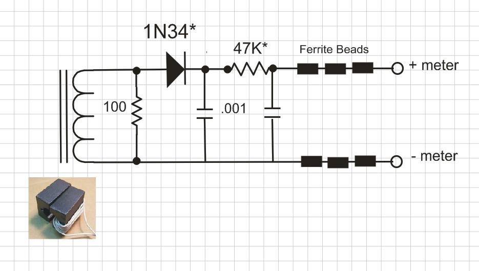
100
ohm load resistor is not critical. 47K resistor can be up or down in value
to suit your meter. Ferrite beads added to decouple the line going to
the meter. If your meter wiring is short the beads probably will not be
needed. Any general purpose diode will be fine.
TIP: Remember that the transformer reduces the current to a value that can be used by the microamp or milliamp meter. Fewer turns results in an increased meter reading but can also result in a very slight impedance "bump" in the line. More turns results in decreased meter reading and less disturbance to the line. I only operate on bands below 20 Mcs so I just ignore the possiblity of an impedance "bump".
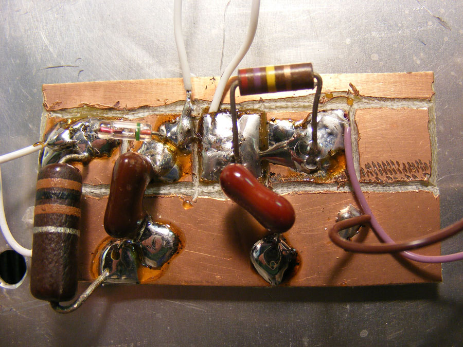
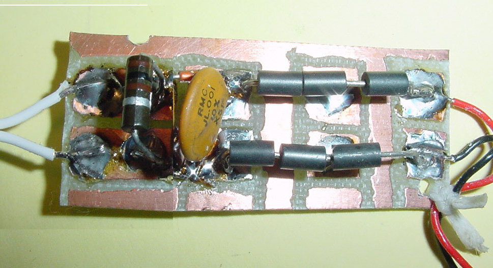
Another
detector board that was permanently installed in the output of an antenna
tuner. The two white wires at the top go to a front panel mounted variable
resistor (pot) to allow adjustment of the sensitivity of the meter.
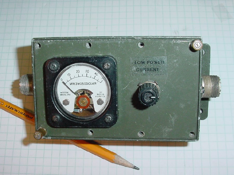
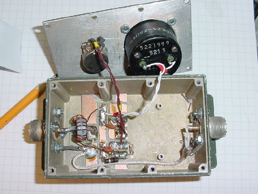
A
low power current indicator used for Field Operations. Note the variable
pot. Monitoring for maximum current and watching a ME-61 field strength
meter for a peak that coincides with the peak in
current is an excellent way to monitor your "system".
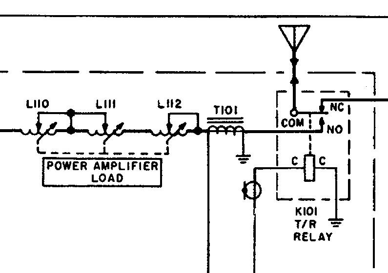
The
Collins PRC-47 uses a transformer (T101) to monitor the output current,
note its location just before the antenna relay.
In this example
only a few turns were utilized on the ferrite pickup and no real difference
in tuning was noticed on the open wire line.
TIP: Put a
current sensor on the output of your antenna tuner, tune your system for
maximum current and ignore SWR. etc. Often you will notice that the "Maximum"
current peak of your "system" does not agree exactly with your
minimum reading on SWR meters etc. Tune for maximum current. Hams
will put meters everywhere but ignore the actual output of a Antenna Tuner/Transmatch
etc.
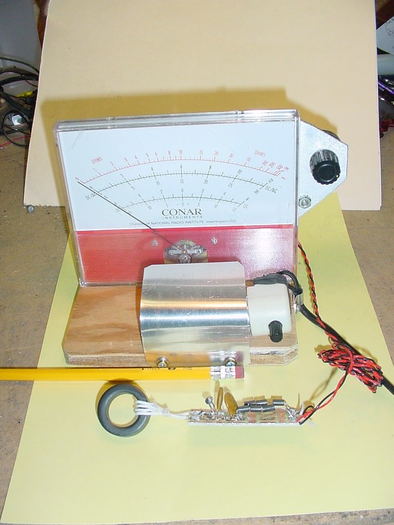
A current pickup and detector system, the meter is mounted several feet away from the detector assembly and the ferrite core is placed on the open wire line as it exits the antenna tuner. The large meter allows you to tune a system while you are on the other side of your "Operations Center". Tune for maximum current, monitor field strength and you are done.