K4CHE GO-9 HF/MF Transmitter Project
                    

                          KCERB


                High Frequency Transmitter Testing Phase    
                                                                                                   A Saga of sorts.


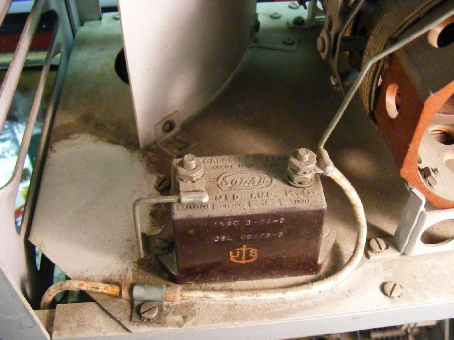
               The HF transmitter had acquired quite a bit of grime but no corrosion was present.
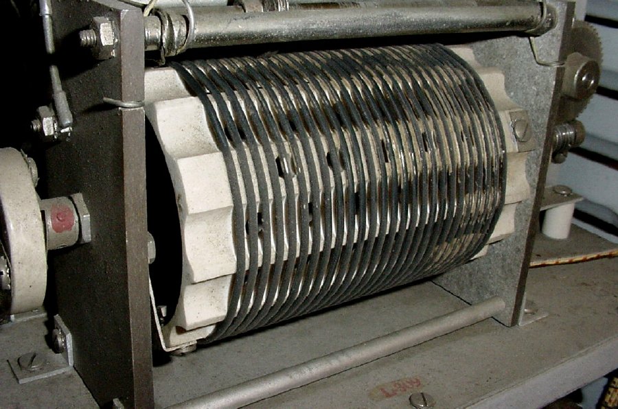
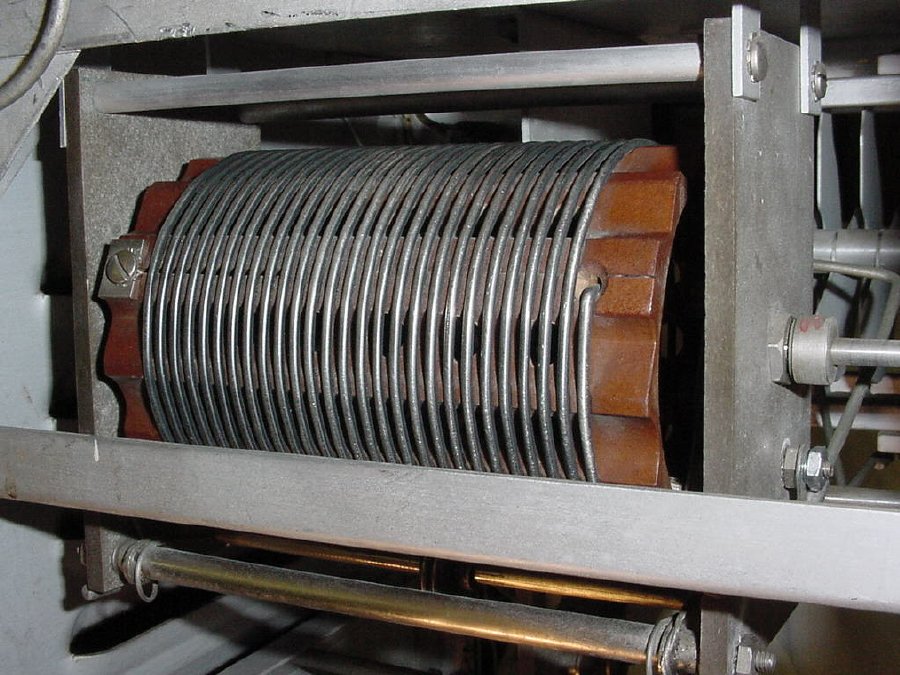


               3M Scotch Brite pads(green) cleaned up the roller inductors. " Replaces steel wool and metal sponges and won’t leave metal slivers in hands or food. Non-rusting and resilient."

                                           http://www.shop3m.com/70071592383.html


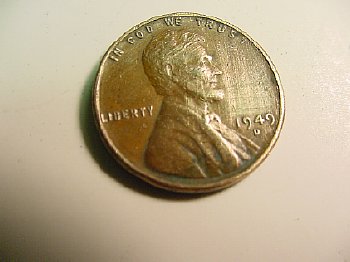
                                     Lucky penny found "heads up" in the bottom of the set.
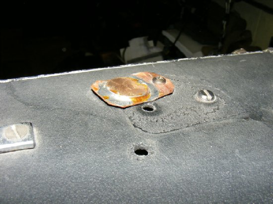


                                 I mounted the penny on top of the transmitter for luck.      
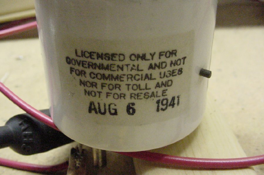


                                                      Interesting date found on the 803 base.


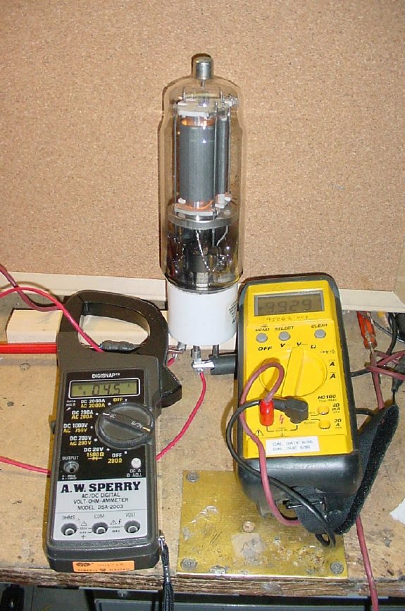
                                            Test jig for filament current on the 803.


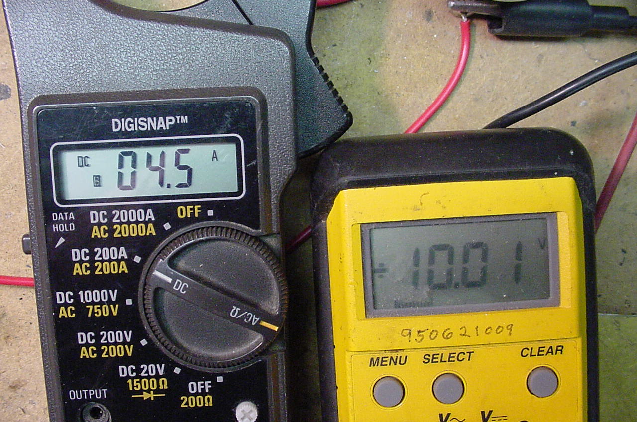
                                                  4 and 1/2 amps at 10 volts.


                                         The 803 is a nice looking tube.


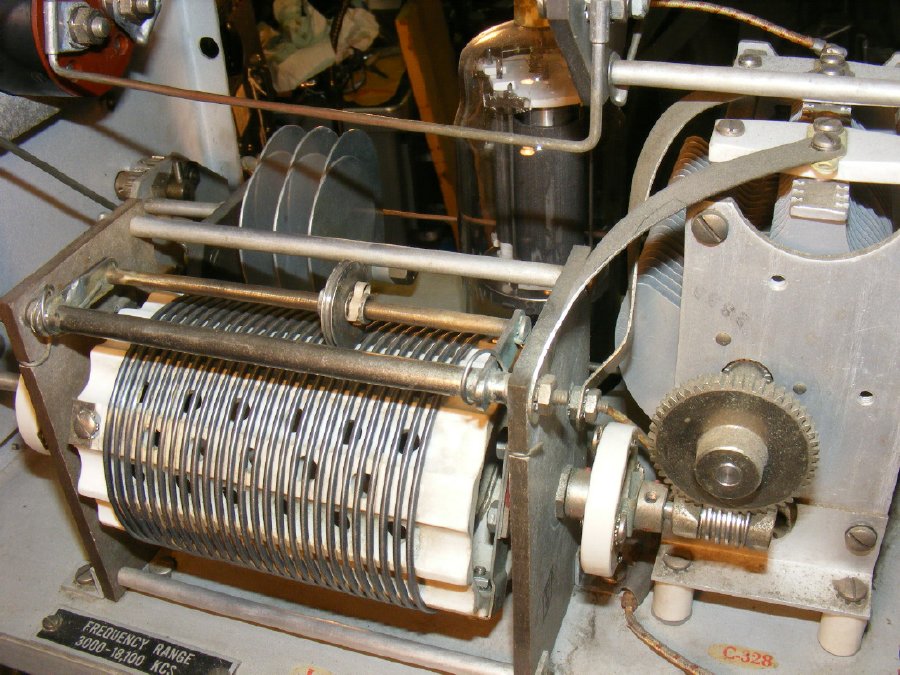
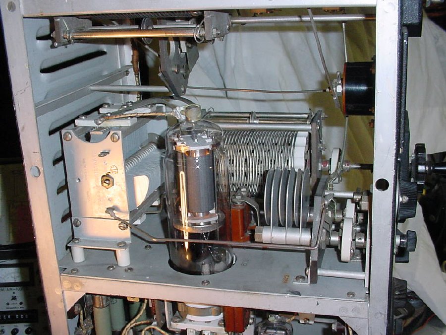
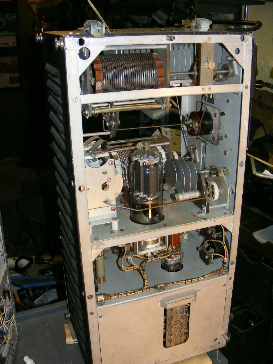
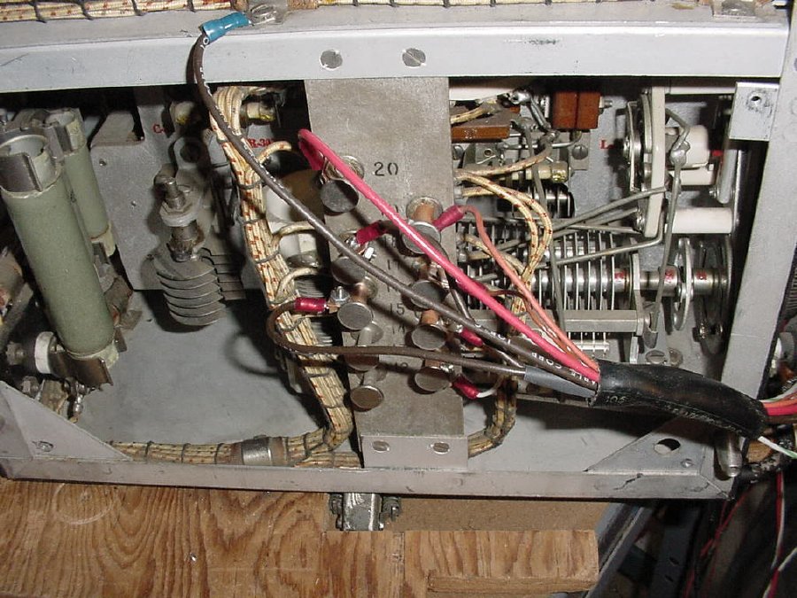
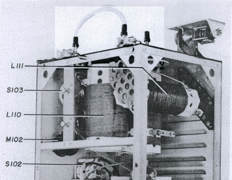
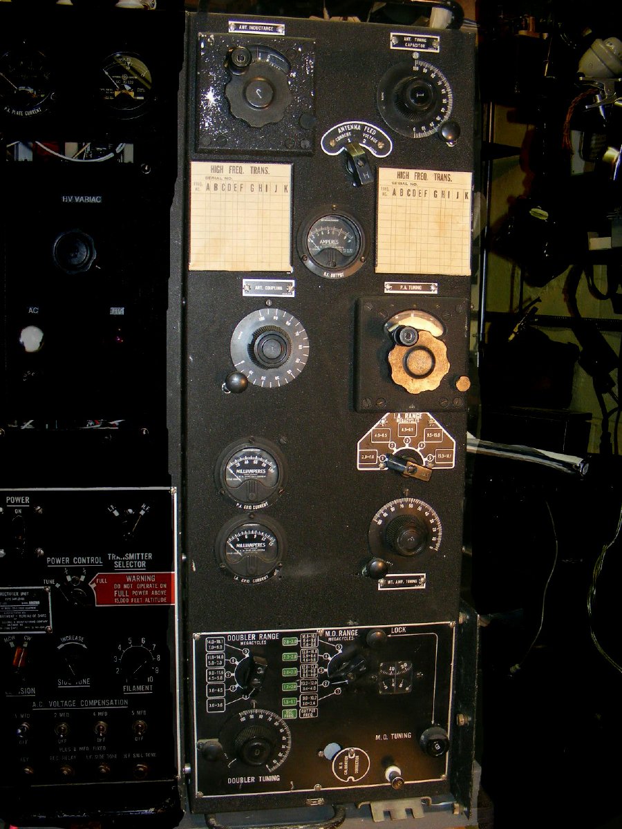
                               PA tuning section. Note that the coil when rotated also drive the variable.
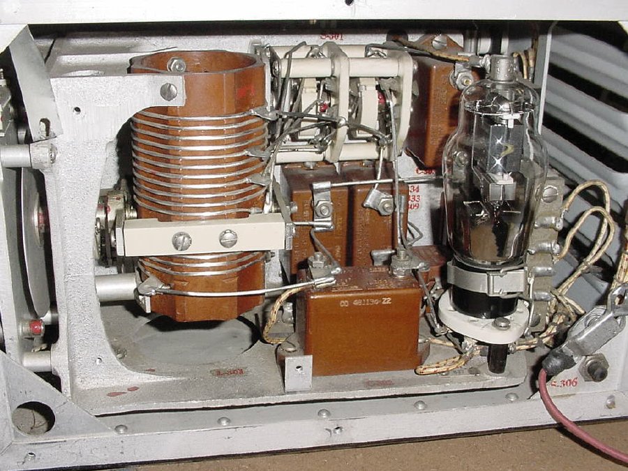
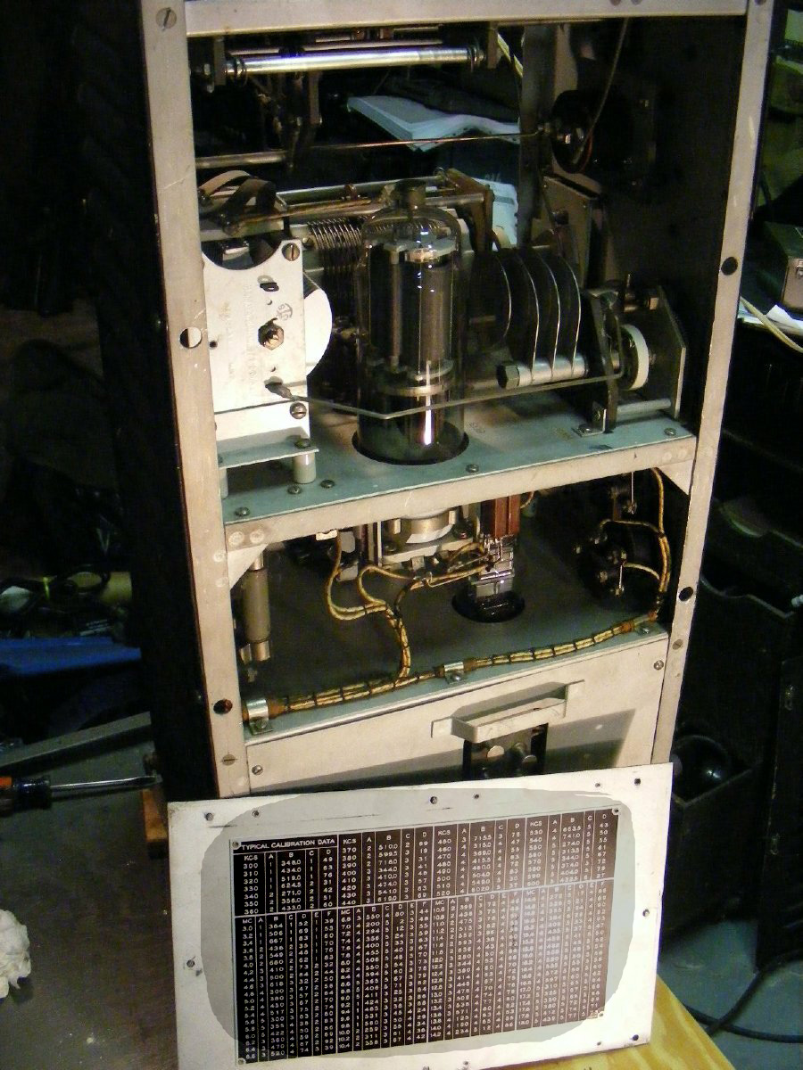


                                        VFO section with a 837 tube. Cover has been removed.


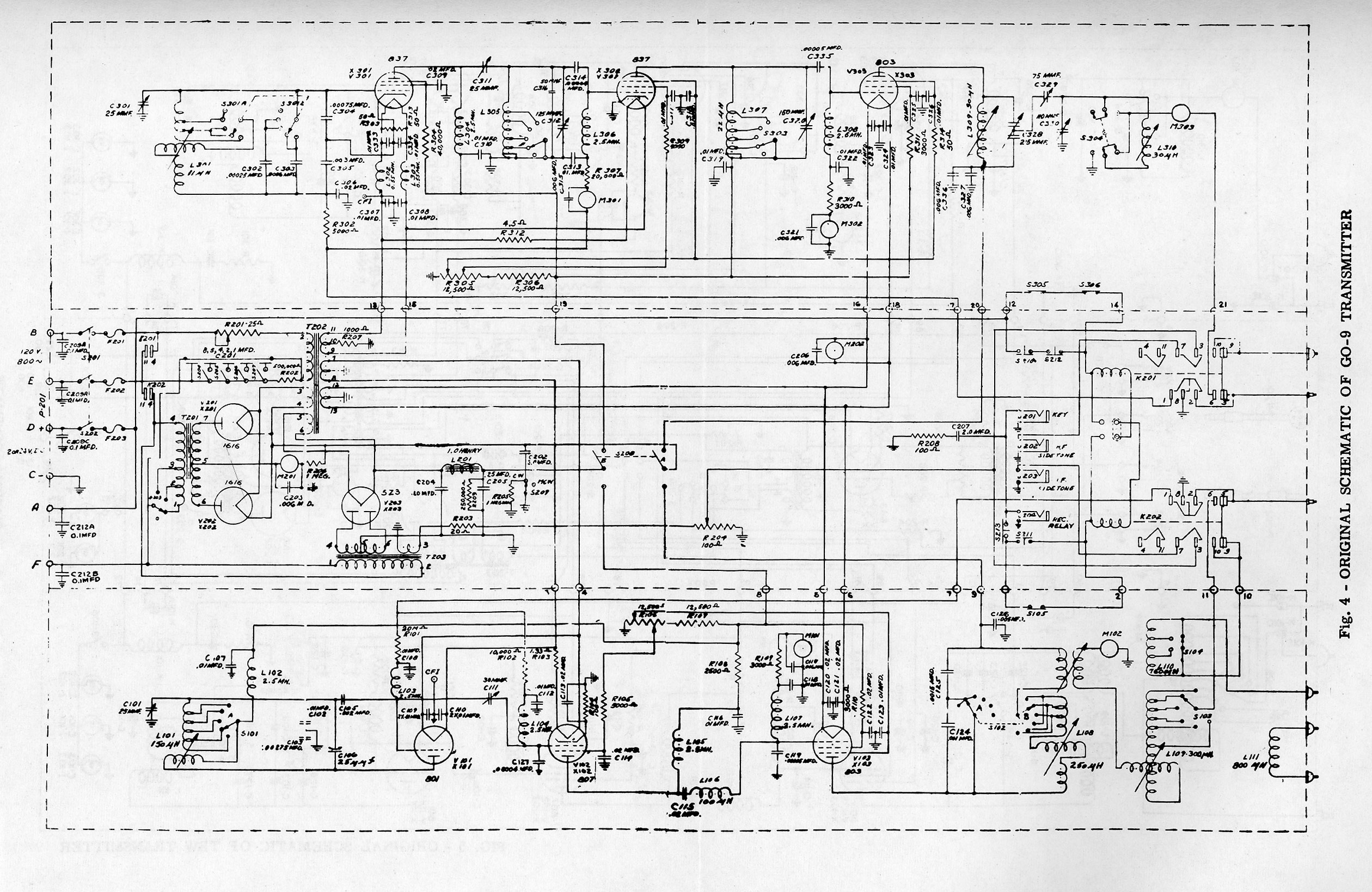
                                                      Complete schematic GO-9


                                       Side view. Meter shown is an RF Amp Meter.


        Left side of the transmitter, note the power supply connections on the bottom and the antenna connection at the top.


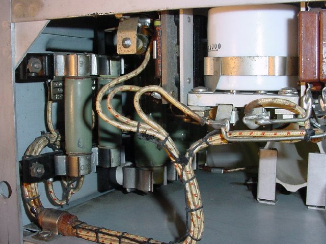
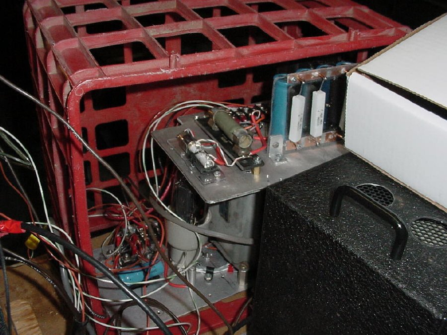
                                          Power resistors mounted in clips.
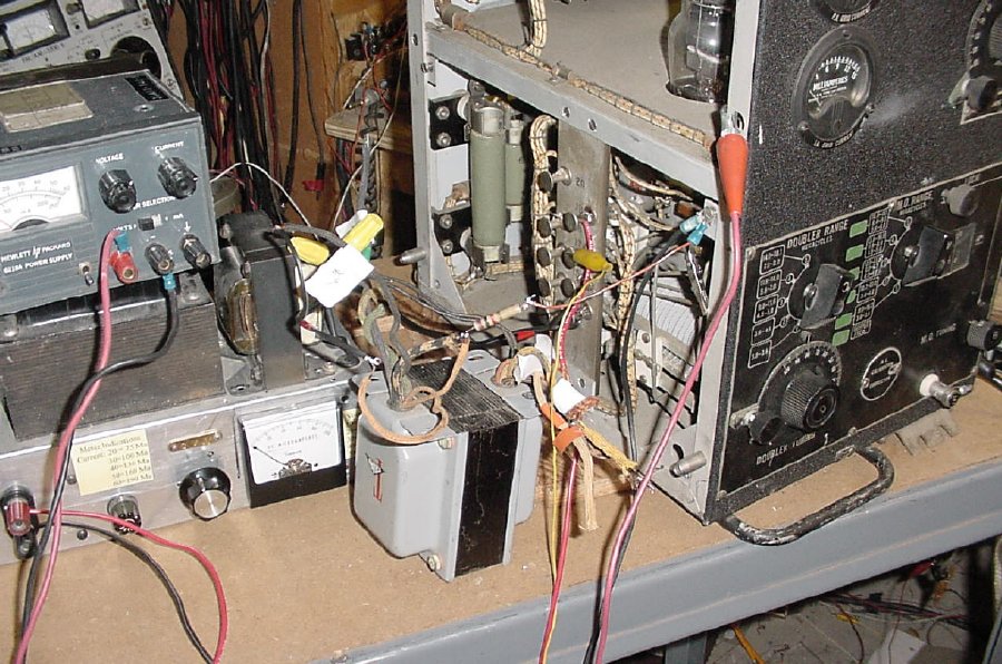
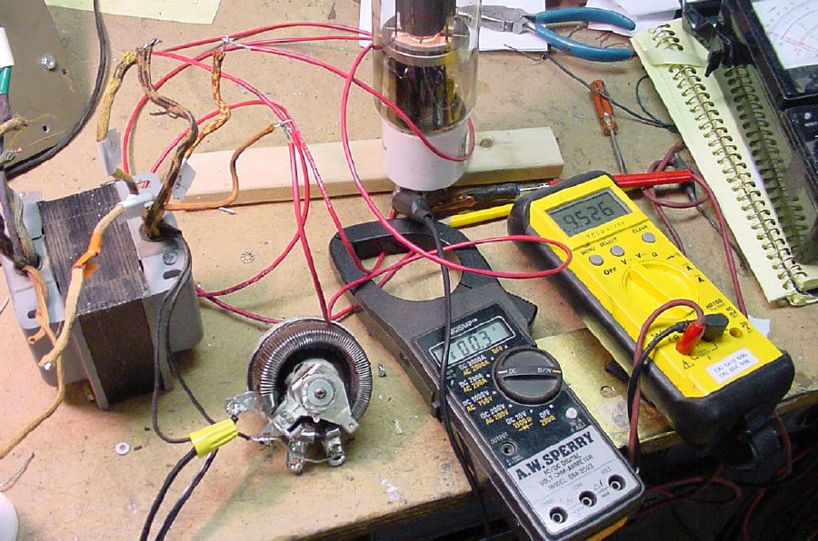
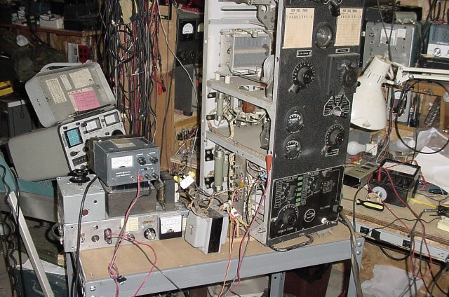


                                          Initial testing.


                           Temporary power connections. Better than those clip on leads. Terminals are designed to make contact with spring type connections show below.


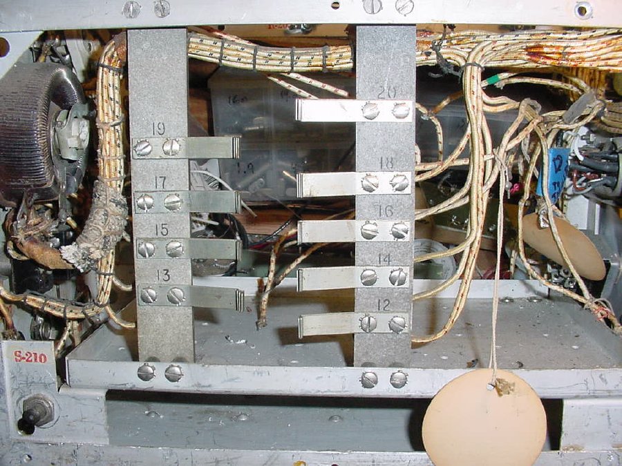
                              Spring connections on the power supply chassis. This board mates with the transmitter power strip.


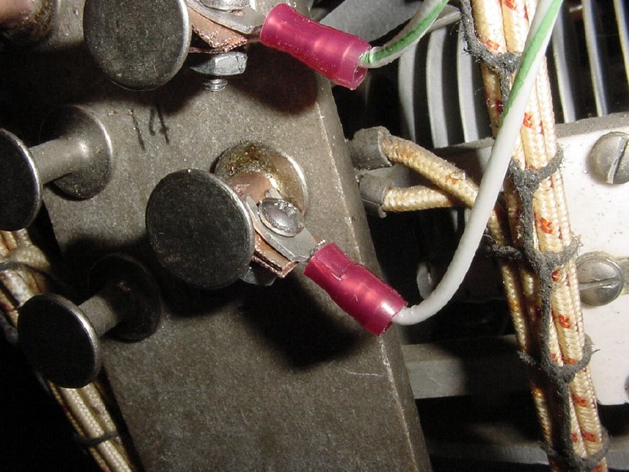
              T power connections were made using copper strips bend around the connector. The strips were held with with 6-32 screws and standard crimp terminals.


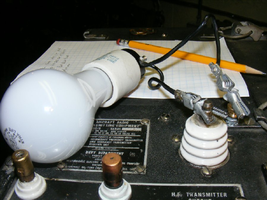
                                         An excellent load for testing.


                          A ground binding post was fabricated by using a 1 inch 8-32 bolt and a knurled nut. This assembly replaced the flat head bolt on one of the latches.


                                               Temporary antenna connector for coax.
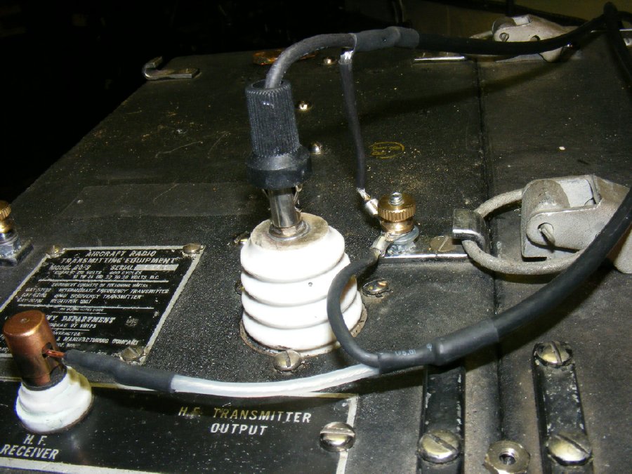


                                  A better antenna connector as suggest by Mike KC4TOS , using Rajah type High Voltage connectors to connect RG-58 coax. Do a "Google" for connector sources. Or check EPay. Cable at the bottom is for the receiver.


    The Rajah connectors look just like the connectors shown on the page from the manual.


         Target  control settings are printed on the inside of the VFO cover to aid in initial tuning.


                       The HF transmitter on "life support".


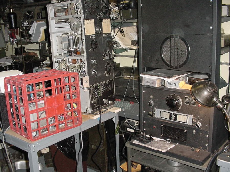
                                 My setup during a "CX" contest.


                The CX contest operation was an excellent test for my prototype power supply boards.


                                Overall a neat looking transmitter. A little on the heavy side. Lots of knobs and meters. Takes about 3 hours to tune up.
 
                                                             Return to GO-9 Index  
                                                                       Return to K4CHE Index