 GRC-109 Antenna Relay
 Problem: The GRC-109 and RS-1 do not have a proper antenna switching system from Transmit to Receive.
The loses are tremendous
on receive. On 40 meters I measured 35 dB loss with all controls peaked
for best reception and when controls were not peaked all most 50 dB loss
occurred. We used to call this "Signal Suck-Out."
"Signal Suck-Out" was a
very common problem for hams when "Electronic" TR switches were
first introduced in the late 1950's and early 1960's. The signal loss
while receiving was usually corrected by using a separate antenna on the
receiver but at hamfest and military rallies where I utilized my 30 foot
AT-1011 it was not convenient to string out an addition wire.
CLICK to enlarge
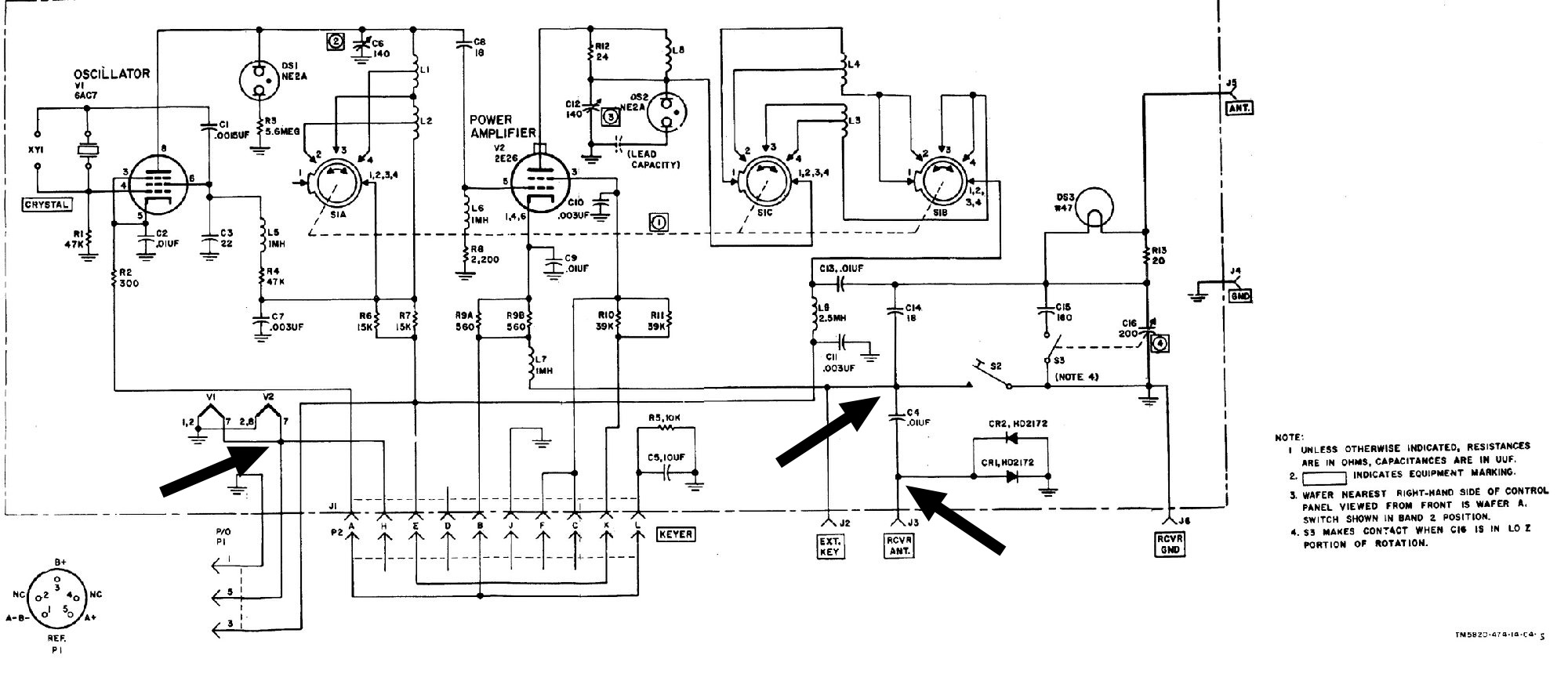
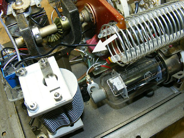
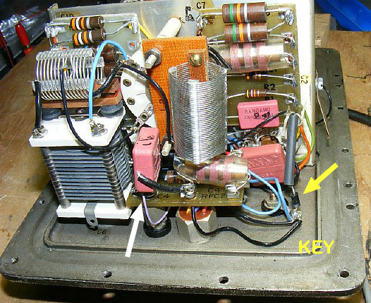
Black arrows point to areas where voltage and keying connections will be made. Note that the receive antenna input and transmitter keying circuits are not changed.
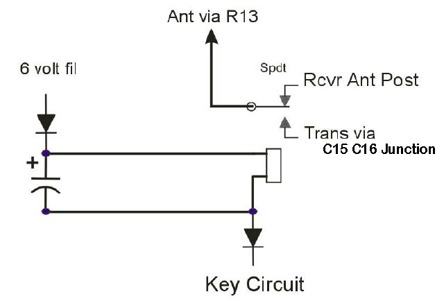
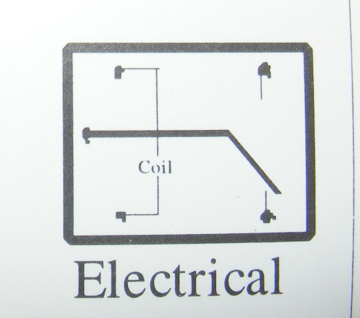
The solution is to use a keying relay for the antenna. The RS-6 radio used a keying relay for antenna switching so we decided to try it on the GRC-109/RS-1. The relay coil is powered by rectified DC from the 6 volt filament supply line. The secret to the keying circuit is to use a isolation diode shown above so as not to disturb the sets keying. The filament line is rectified a single diode and provides about 4 volts for the DC relay.
The diode shown in the KEY circuit is the secret to the circuit and allows the relay to be keyed without disturbing the transmitters keying circuits.
The terminal board for the 6 volt filament is located underneath the band switch. Look for a green wire connection and this will be the tap for your relay power.
The Green 6 volt filament wire is located on the center terminal of the board. This will be your tap for powering the relay. Just tack on your connection with a soldering iron.
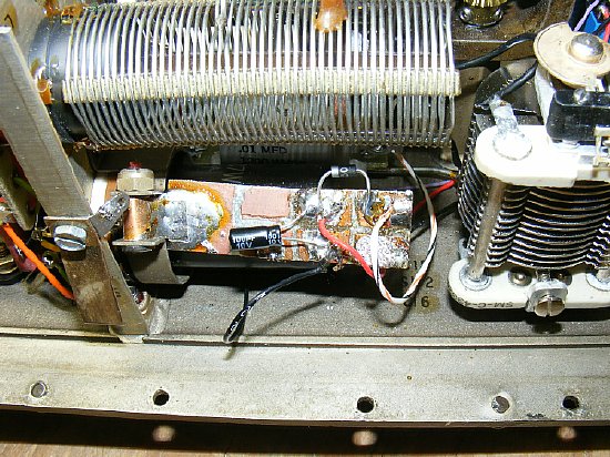
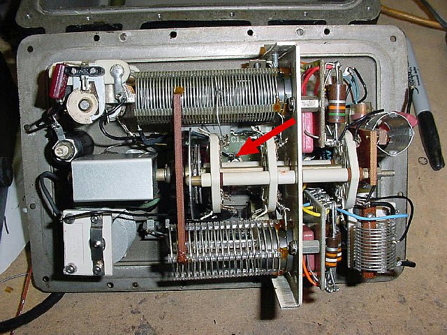
I
used a piece of PC board made with a Dremel tool for the connections.
The board is held in place with a copper strap wrapped around the 6AC7
tube clamp bolt. The PC board is a little messy as I have tried several
circuits and finally settled on a simple diode to rectify the filament
voltage and a 100 uF filter capacitor. You can play with the capacitor
values but 100 uF produced decent keying.
The striped
wire goes to the 6 volt filament terminal. The Black wire goes to the
transmitter "Key" terminal. Red wire goes to the relay coil.

The Philmore line of relays is an excellent choice. Search for Philmore 86-105. The 3 volt version 86-103 can also be used. It is amazing that the Philmore company is still around.
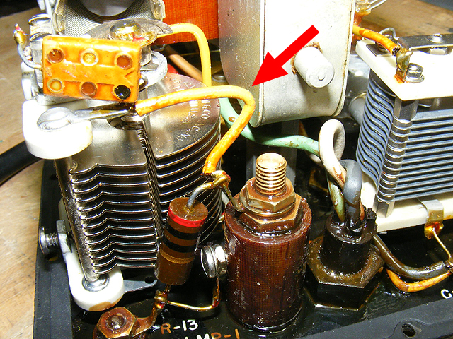
Before Photo- Red arrow points to the antenna lead from the junction of C15 C16 and R13 on my RS-1. Disconnect the wire (yellow) running from the top of resistor R13 DS3 bulb connection to C15 and C16. Unsolder at C15- C16 junction. This antenna input output wire will be connected to the center terminal of the SPDT relay.

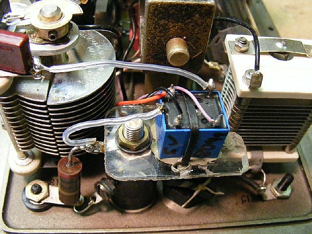
Lift the antenna feed wire connecting R13/ bulb DS3 to C15 C16 Junction and connect to the relay mounted on a small piece of lexan held by the bolt on the bulb housing. I replaced the spaghetti tubing.
Red-
Coil voltage
Black- Key line
Purple- Rcvr antenna
Clear- Antenna Connection to R 13 and and Transmitter out.
Relay wiring diagram bottom view.
Another view of the relay installation. The relay is mounted on a piece of lexan which is held by the bolt on the bulb holder.
White arrow points to RCVR antenna terminal and has my purple wire tack soldered on. Yellow arrow points to my relay keying diode connection on bottom of the insulated key (S2) terminal.
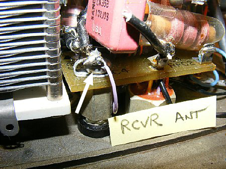
The RCVR antenna post terminal connection where my purple wire is tack soldered on. While you have the set open you might check the receiver antenna overload protection diodes CR1 CR2 which are located on this board.
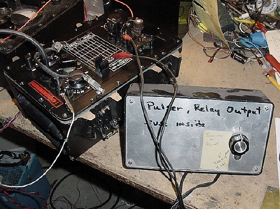
I did an initial test using my home brew pulser and keyed the GR-109 for a 30 minutes. The keying was clear and survived the pulse test. On the air testing revealed yet another plus - - - QSK is fairly adequate - - - not as good as using pin diodes for switching but easily useable.