LS-671/VRC Loudspeaker Control Unit
Power
and Hook Up Instructions
Note: Changes
added October 10, 2018 - please reload the page.
What can I do with a LS-671?
Possible uses:
1. Use as a external amplified speaker
2. Use it to interface the noise canceling H-250 handset or the M80/U microphone to a marine SSB or "civilian" radio. You can hide that Rice Box and remote the audio.
3. Use to remote your radio. Probably good for couple of hundred feet. Limiting factor is the PTT line.
4. Connect it to a BC-1306 or BC-474 at the next rally and see what happens when the experts drop by.
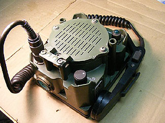
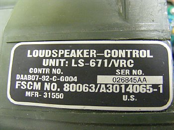
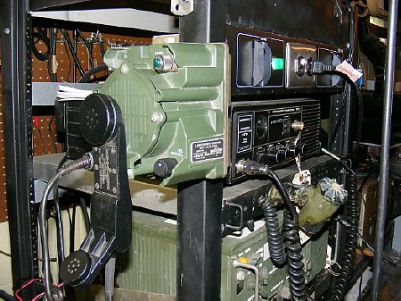
LS-671/VRC
Speaker. Brooke's site PRC-68.com has quite a bit of information about
this unit. There are numerous sites with information about the LS-671
but they might be missing voltage levels, current consumption and correct
pin connections. I have posted pin information below that worked for me
and my applications.
Brooke's Military Information, N6GCE http://www.prc68.com/I/RT1439.shtml#LS-671
Its a great little unit, use it with the H-250 handset or just utilize the internal microphone and speaker amplifiers. Its a great stand alone speaker amplifier unit or a microphone preamp or both.
.jpg)
CLICK to enlarge
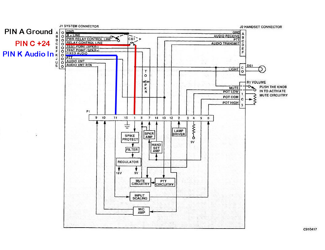
Here is a page lifted from TM-5820-890-30-4 one of the SINCGARS manuals.
TM-5820-890-30-4 PDF link
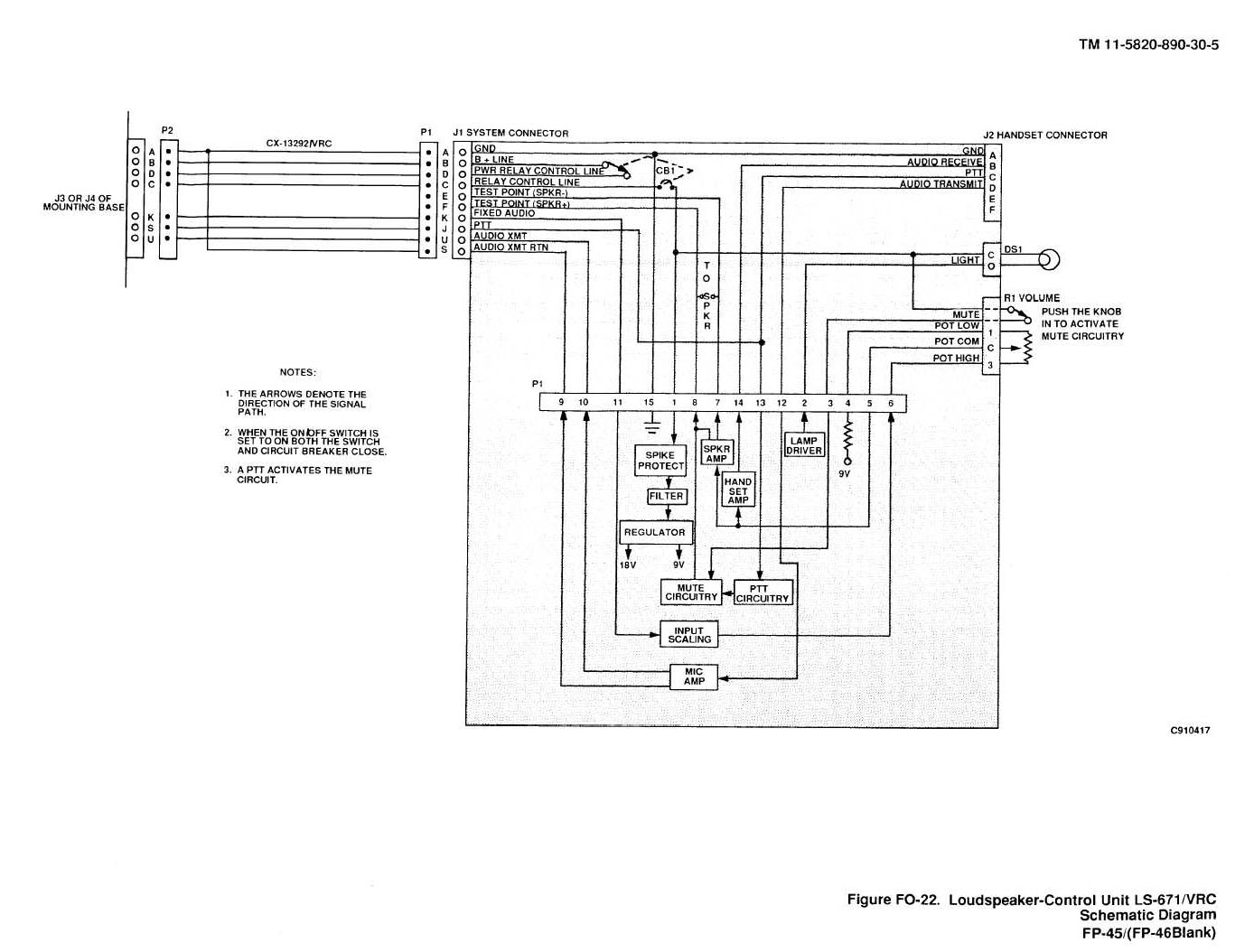
Schematic CLICK to enlarge
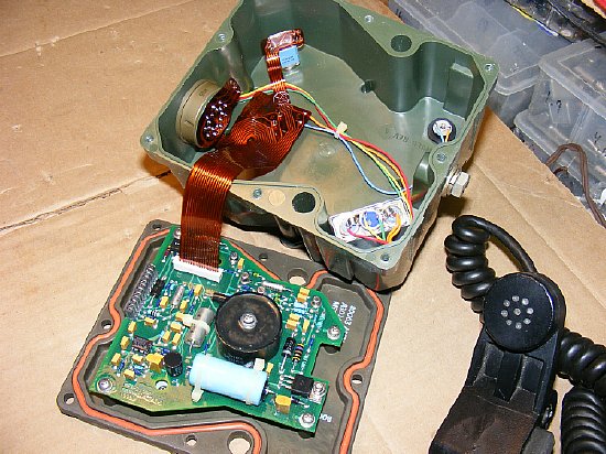
It's a nice looking unit on the inside.
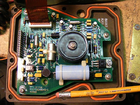
There are no internal adjustments.
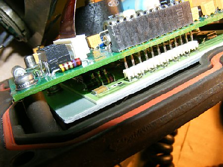
There is a "secret" board hidden under the main board, most of the components on it are surface mount.
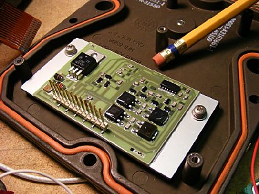
The 2nd board. Note the large LM317.
Main
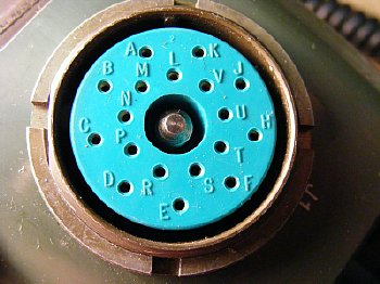
System Connector J1
The main system connector is a standard 18 contact connector used in the
VIC (Vehicle Inner Comm) system. The contact pins are lettered and are
easily identified. Power up the unit via Pin C (relay control line) (see
schematic) and Pin A (GND)on the main system connector. The voltage from
Pin C goes through the switch/circuit breaker combination and provides
power to the 9 and 18 volt internal voltage regulators.
More connection information below.
While you are searching through your connector box you can test your unit with some temporary pins. "Improvise Adapt Overcome"
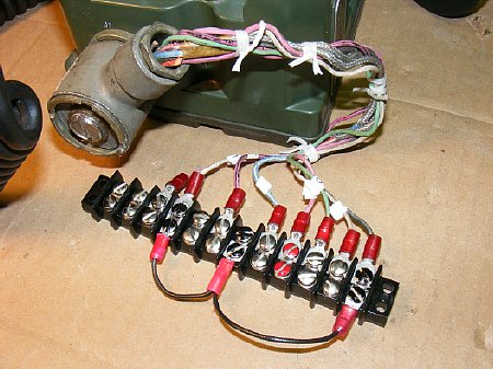
I fabricated a "break out" strip.
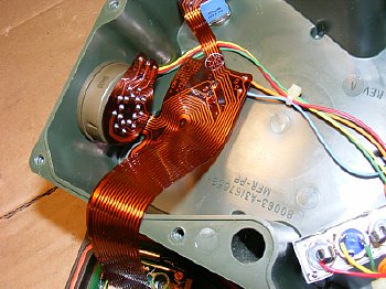
"Ribbon" connections on the main system connector. Fragile - - - Scary, this might be the reason so many of these units are available at flea hamfests etc. Check these solder connections on the main system connector and ribbon connections to the main board if it comes time to troubleshoot.
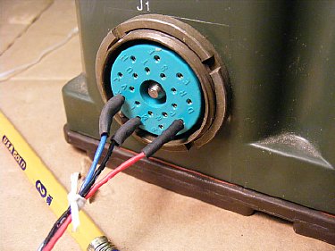
WARNING: Don't wiggle the main system connector when removing the plug- pull straight out or you will be sorry. Just unscrew the wing nut and carefully pull straight out.
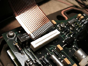
A loose ribbon connector is easy to fix, pull the white clamp away from the board, insert the ribbon and reseat the clamp to hold the ribbon.
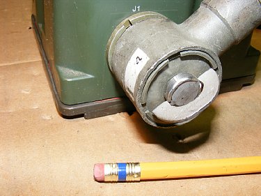
Don't wiggle this connector! Unscrew the mount bolt and pull the connector straight out. When inserting note the location of the 'key" on the box connector and on your plug its not on the top but at the 8 o'clock position.

Connector tip: When searching through the piles of cables at the military vehicle show, don't be afraid to purchase a cable this is missing the "wing" on the hold down bolt assembly. The cable will be much cheaper in price. Removal of the outer metal disk will reveal a slot that can be turned with a screw driver or a dime. Modification unauthorized by the TM but works great in the field.
Improvise . . .

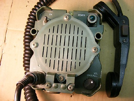
The
plastic speaker is kind of interesting speaker grill has slots to pass
the audio but no water proof membrane but looks to be pretty water resistant.
An interesting note and link below by Steve KM4V:
"Have enjoyed and used the resources on your site....Many thanks! Thought I would pass along a possible discovery re: the LS-671, I think the speaker in these units is a Piezo unit, just like or similar to the MISCO MP-1103, or at least that is what I seem to recall from my research."
http://www.miscospeakers.com/speakers/MP-1103
http://www.miscospeakers.com/speakers/MP-1103
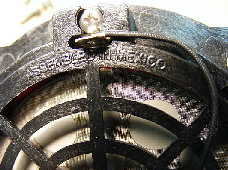
More tax dollars to another country.
Basic speaker amplifier operation
CLICK
1. Provide power to Pin C, Ground to Pin A of the main system Connector.
2. Feed audio into Pin K , ground to Pin A of the main system connector J1.
3. Turn set On.
4. Adjust volume, make sure the volume control switch is pulled out and not pushed in. Pushing in the volume switch will mute the speaker but does not mute handset audio.
Speaker Amplifier Bench Notes:
With an input of .8 volt PP the output measure at the speaker test point Pins E or F was 5.3 volts PP resulting in approximately 15 dB gain. An input of 100 mV resulted in output of 600 mV, An input of 200 mV resulted in output of 1100 mV etc. NOTE: 9 volts is present on test points E and F, use a .1 capacitor on the ground of your scope probe when checking levels or when using these points to feed other devices use a .1 coupling capacitor on one lead.
Current Consumption:
Power 24 volts, 1000 cycle tone on the input at .5 volts PP. Low audio volume setting resulted in 80 mA current, High Volume 95-100 mA. System idle about 70 mA. With a lot of audio to the point of distortion current draw was 150 mA.NOTE you can remove the light bulb (DS1) from its holder and reduce overall current drain by 40 ma. Turning off the main toggle switch/circuit breaker completely powers down the unit and reduces input current to zero. Note during battery operation you have to turn the LS-671 speaker set off other wise you will eventually drain the battery. An alternative would be to let the transceiver supply the power through its "accessory" jack.
The Direct Support Maintenance manual TM-5820-900-30-4 list current consumption as 150 to 500 mA.
NOTE: The amplifier does not have a fuse and I am not sure about reverse polarity protection as I did not test it.
Removing the bulb will lower the current consumption by 40 mA, this might come in handy if you are running the speaker temporarily on two 9 volt batteries.
Microphone Preamp Operation
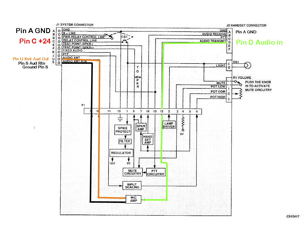
CLICK
1. Apply power to the unit.
2. Low level microphone audio input to Pin D of the U-229
connector.
Ground to Pin A of the handset connector.
3. Amplified microphone output will be present on Pin
U (Audio Smit) of the main system connector.
Be sure and ground Pin S (Audio Xmt Rtn)
Bench Notes:
With 50 mV in on Pin D of the Handset connector J2 (U-229 type) with Ground on Pin A resulted in an output of 2 Volts PP on Pin U (Audio Xmt) of the J1 system connector , a very large increase (over 30 dB) and this reduces to about 1 volt PP when under load of a typical radio microphone circuit. With a typical H-250 handset voltages obtained were 2 to 5 volts PP depending on voice peaks which is reduced under typical circuit load to about 1 to 2 volts PP. Most radios will require an additional pad to reduce the voltage.
Note: PTT does not have to be activated in order to use the transmit audio amplifier circuit. (info - typical voltages for a GE mic element is 1 volt PP, typical handset H-250 mic audio is approximate 50 mV so the LS-671 microphone output is quite high.
PTT operation
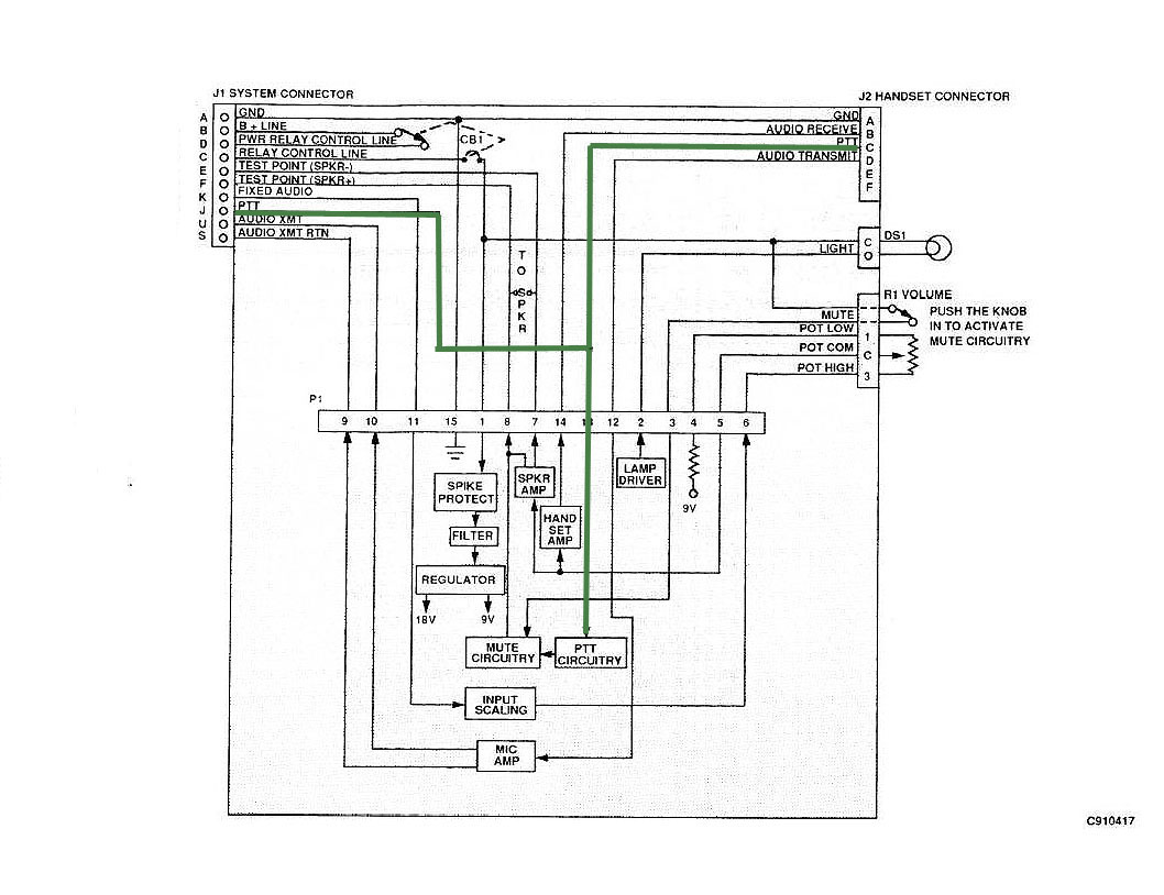
CLICK
The PTT circuit is a direct connection between
the handset and the system connector. There are no relays or solid state
switching involved just the contacts on the handset. Remote operation
requiring the PTT circuit is probably possible up to a hundred plus feet
depending on the radio. The PTT line also activates the Mute circuits
for speaker muting but does not mute the handset. Resistance measurements
indicate a internal system resistance of 10-20 ohms when using the H-250,
this resistance may hinder remote operations.
Remote
control Contacts
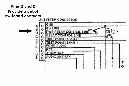
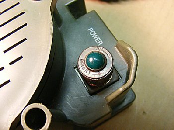
The main toggle switch has an extra set of contacts
that allows pins B and D on the system connector to make contact through
the switch - this contact pair could be used to power up a device but
you will be limited due to the current capability of the switch contacts
which is unknown best guess 10 amps.
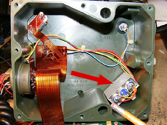
Arrow points to the main power switch /circuit breaker. Note the extra set of contacts in the center. This is used for Pins B and D on the system connector for possible control of another system or radio.
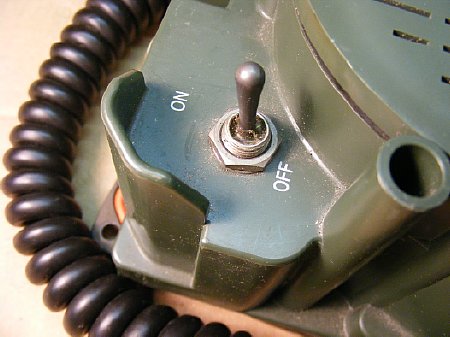
The circuit breaker function of the toggle switch is rated at 2 Amps. During the bench testing the breaker "tripped" at around 2.2 to 2.4 amps. On this type of circuit breaker the toggle "bat handle" portion of the switch will physically move to the OFF position when an over current condition exists - you will hear the click. To reset this breaker move the toggle back to the ON position. Sometimes this type of circuit breaker requires a cooling period prior to reset. Investigate before resetting.
You can use the set at a lower voltage but when voltage drops below 13 to 13.5 distortion starts on the audio amplifier circuit
Transmit audio works OK down to the lower voltages.
There is a clip located below the speaker for hanging up the H-250

Your tax dollars at work. Buy one at the next ham fest or military rally or ePay.