
PRC-10 Maintenance/Ops Section 2

a.
Power for the Radio
b.
Power circuits
c.
Voltage checks
d.
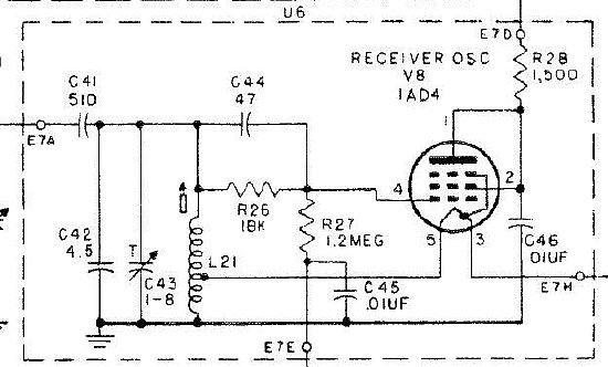
Receiver Oscillator notes
e.
Tube info
f.
Ops and Trouble Shooting tips
g.
Handy Items.
h.
New Squelch mod (encode only)
i.
Calibration Info
j.
Squelch
k.
Transmitter Alignment (How to get on Frequency)
l. IF Module Repair
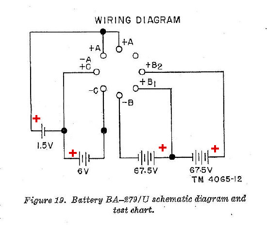
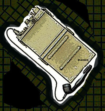
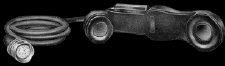
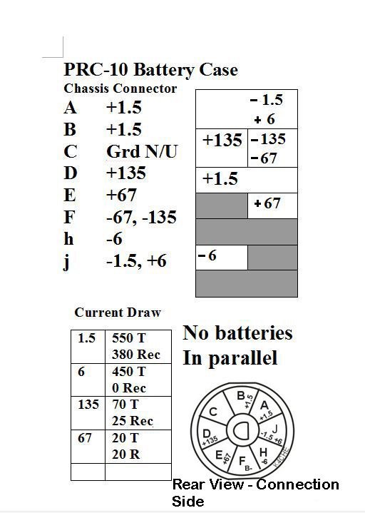
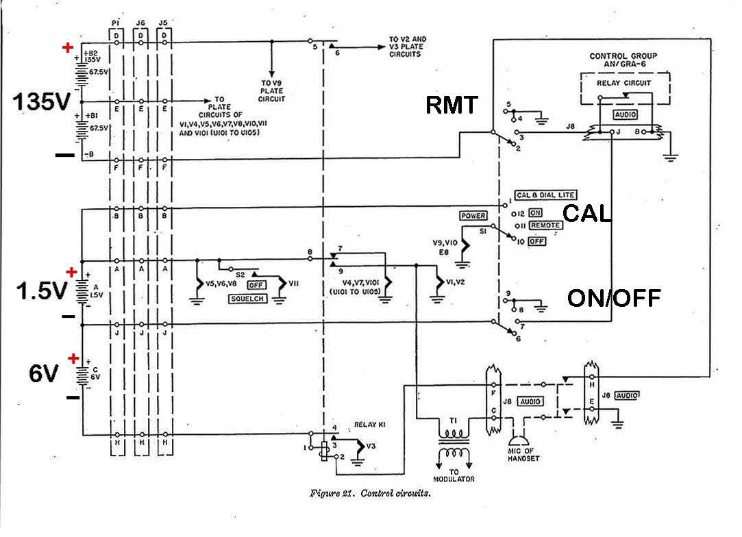
The battery wiring diagram can look
daunting. Basically the circuit is comprised of 3 battery sections.
The
sections are: A low voltage 1.5 volts filament battery - A low voltage
6.0 volt filament and relay battery - and a high voltage battery that
has a center tap.
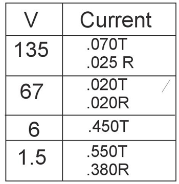
PRC-10
Voltage /Current Bench Measurements. This chart
may be revised as additonal sets are tested.
The 135 volt battery has a center tap to provide
67 volts. The 1.5 volts buss is utilized for the minature tube
filaments. The 6 volt buss is used for the transmitter final tube
filament and to provide voltage to the RT relay. Since the transmitter
filament is at a minus potential in reference to chassis ground it provide
bias to the transmitter tube.
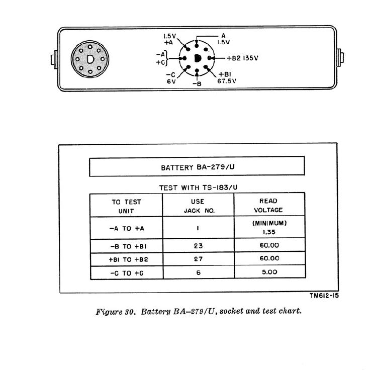
Figure 30 taken from the PRC-10A manual.
k4che
A
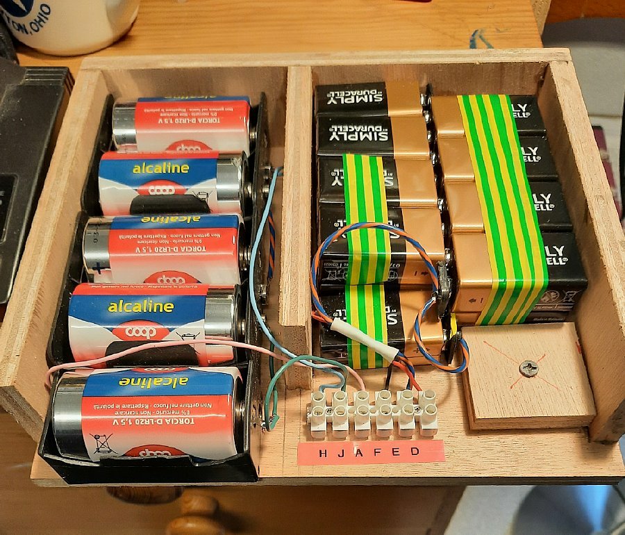
homebrew battery pack for the PRC-10 can be comprised of 9 volt batteries
and D cells. Sixteen (16) 9 volt batteries are used in series which provides
a no load voltage of 144 volts for the high voltage. 4 D cells are utilized
for the 6 volt buss and a single D cell is used for the 1.5 voltage. Pack
construction details below.
Click
to enlarge
Giovanni iz5pqt fabricated a nice and very functional wooden enclosure.

Nice
home brew socket using PC board material and pins from an octal socket
.
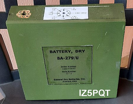
IZ5PQT finish his battery with a nice outer cover and diagram.
The
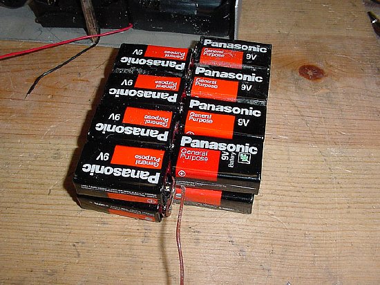
9 volt batteries can be clipped to them selves in series which will eliminate
a lot of tedious wiring and the result is a fairly reliable battery pack
as it eliminates those pesky cheap 9 volt battery connectors.
Note the use of "Dollar Store" batteries for the 9 volt
battery pack. Cheap and they easily last a entire summer or military rally
season.
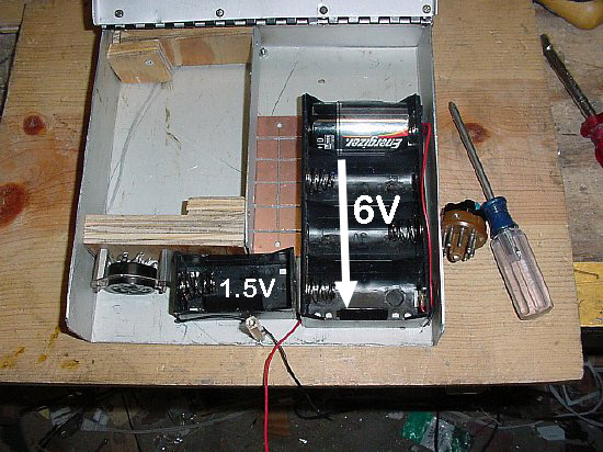
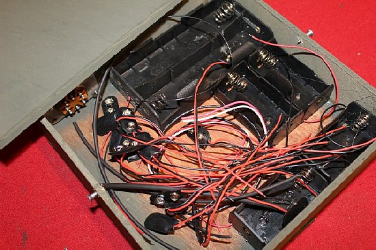
The 9 volt battery group is held in place with small L shaped strips of plywood. This case used a 8 pin octal socket as a connector. The orginial connector on the RT unit case was MIA due to Ham Hacking.
The original chassis connector can be purchased from Fair Radio.
Fair Radio BA-279CO-ZZ4 includes male and female and mounting ring.
The odd ball "L" shape to hold the 9 volt batteries in place is easily created with one of my favorite tools. Titebond.
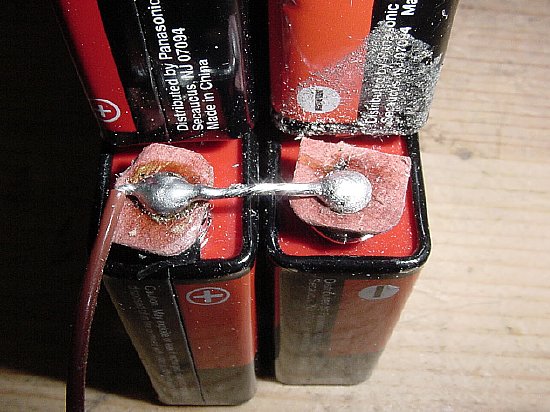
The B plus battery pack center tap can be fabricated out of a battery connector cut in half.
k4che
A
seperate D cell is used for the 1.5 volts. Note the "voltage distribution"
board in the center fabricated from a piece of copper clad printed circuit
board. Photo below.
DO NOT UTILIZE 1.5 volt Cells in parallel. If one cell is slightly lower in voltage the other cell will attempt to charge it and the battery chemistry may change with resulting over heating of both cells.
This "Run Away
Phenomenon" has been experienced by several military collectors
including WA5CAB and myself with the most common D Cell malfunction that
has been reported was when using the FT-501 D (BC-611) cell holder which
places the D cells in parallel. If you insist on putting 2 D cells in
parallel then use batteries with same date code and out of the same package
- check for equal static voltage prior to installation. Do not store the
battery pack in this parallel configuration. Remove the D cells in parallel
when placing the battery pack in storage or on the shelf inside your home.
Another Safety
Tip: When discarding those weak 9 volt batteries cover the terminals with
tape so that they will not become shorted to metal in the shop trash.
Batteries have a unique characteristic of rejuvenation. Don't just throw
them in your junk drawer either without covers.
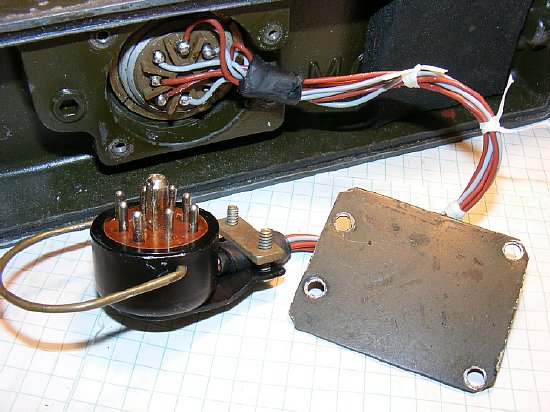
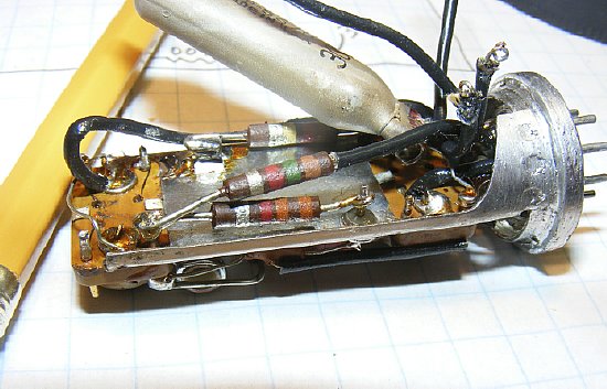
Rewire the Receiver Transmitter case to eliminate rotten wiring problems and to allow for a longer cable.
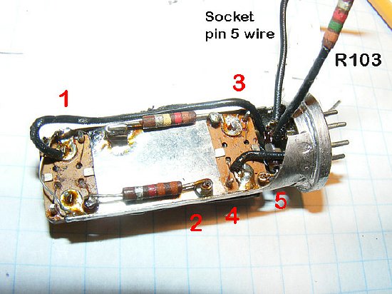
The voltage "distribution board" was fabricated from a single sided printed circuit board.
Wear safety glasses.
The
"Distribution Board" pattern is shown in the upper right.
Socket wiring diagram is a REAR view.
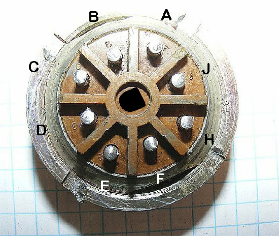
Connector
Rear View
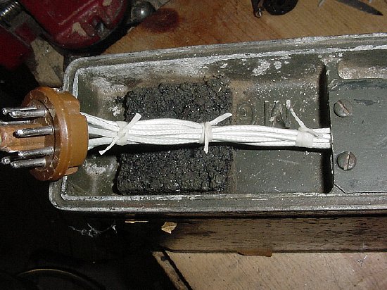
My
five dollar ($5) hamfest PRC-10 was missing the connector for the main
RT housing. So I substituted a 8 pin octal.
"Improvise
- Adapt - Overcome"
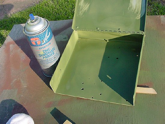
"I love the small of zinc chromate in the morning."
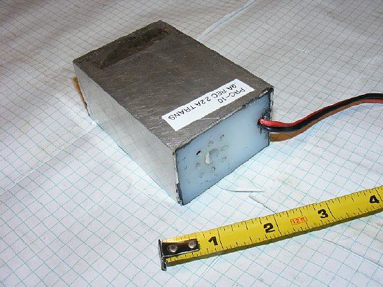
The Italian Inverter works very well and is low noise on receive and transmit. The inverter utilizes a 6 volt battery and requires .9 (point 9) Amps on receive and 2.2 (two point two) Amps on transmit. The 1.5 volts is regulated but the 6 volt output is connected straight through from the source battery.
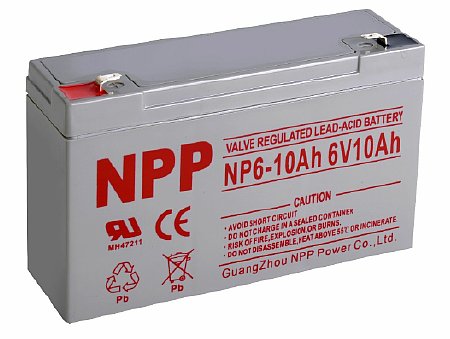
The
Italian inverter requires a 10Ah battery and the combination of inverter
and battery easily fit into the PRC-10 battery box. It is tempting to
just use 4 D cells for the 6 volts but due to the internal contact resistance
of each D cell there is too much voltage drop. D
cells no workee.
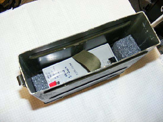
I used Gorilla tape and attached a strap on the sides of the 6 volt battery for ease of maintenance.
When loading the battery case a spacer can be utilized to seperate the bottom battery section with the top inverter section. Note that the battery has the voltage labeled on it to remind me that I need to select 6 volts on my "Genus" battery charger.
Or just fabricate a spacer from card board that was doubled over organizes the battery box. Battery on the bottom - inverter on the top.

BTW: The battery boxes and main receiver transmitter enclosure are not interchangeable between the PRC-10 and PRC-10A. The clamp connectors are different. No workie GI.
ePay battery
that has been listed. Looks very - very busy and possibly has D cells
in parallel.
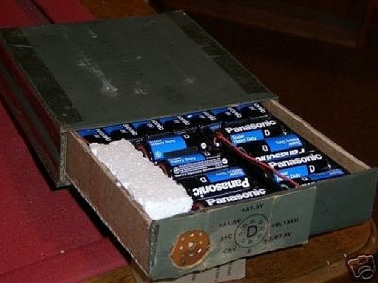
Photo author unknown.
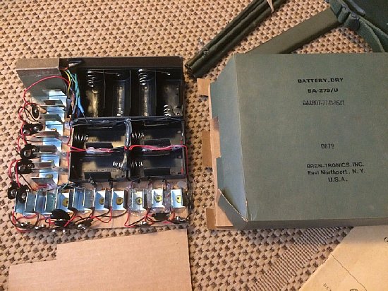
A nice home brew battery using the original BA 279 case and connector. Note the dollar store batteries. Cheep.
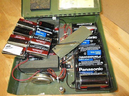
Another ePay battery kit. I suspect the 2 D cells on the right will be wired in parallel to supply the 1.5 volts which is not safe to put into storage. The kit is unique as it is approximately the same size as the original battery and has a cover and utilizes the original connector.
CLICK
to enlarge
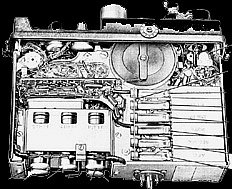
When
trouble shooting the PRC-10 its important to understand the battery power
voltage switching via the main "Power" switch.
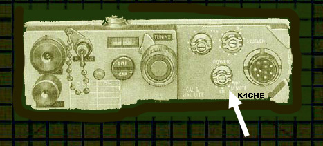
The 4 position Power switch
is divided into 3 switching sections that are ganged turned by the single
shaft. The rotary positions are OFF -REMOTE- ON- CAL.
Note that when positioned to ON
the return or MINUS pole of the 1.5V and 135V batteries are switched to
chassis ground and the Positive pole of the volt battery is also grounded.
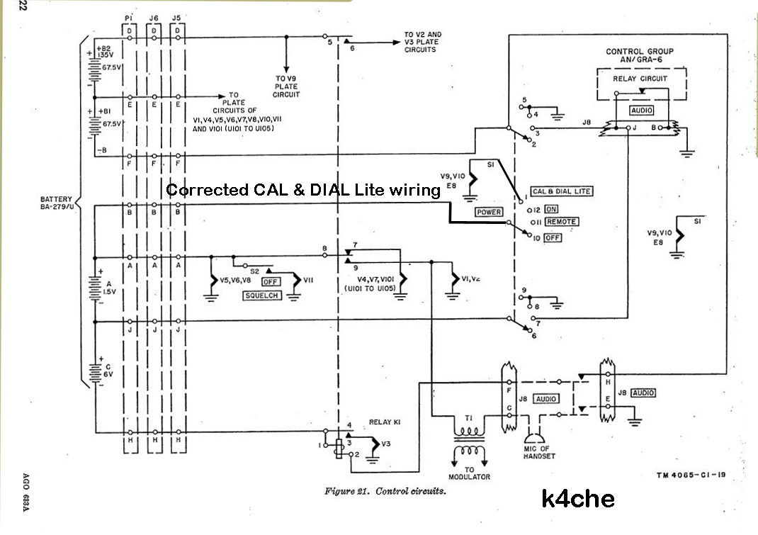
CLICK to enlarge. CAL position wiring corrected.
Most of the manuals depict a minor wiring error on the wafer switch for the 1.5 volt line on the CAL section. The corrected schematic is shown here with the 1.5V voltage feeding the rotary input pole of the switch. Note that when the POWER switch is placed in the CAL position the filaments of the two calibration oscillators V9 and V10 are fed 1.5V as well as well as dial lamp E8.
Note: CAL position on the schematic has been corrected.
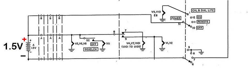
The 1.5 volt filament power is switched by the main power switch and the TR relay K1. When the POWER switch is placed to the ON position the filaments on V5,V6, and V8 will be activated as the 1.5 volt minus is grounded by the power switch. In addition V4, V7 and the IF chain will be active through relay contacts 8 and 7 and the set will receive. When the relay K1 is placed in transmit V4, V,7 and the IF chain lose their filament power - the receiver is quite and V1 and V2 filaments are powered and the set will transmit.
CLICK to enlarge
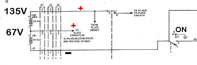
When the POWER switch is place to the ON numerous Plate Circuits(V1, V4, V5 etc. and V9) are activated by grounding the B minus.
These circuits have B + on the plates and screens at all times. B plus is made available at the main TR relay terminal 5 for the V2 Modulator and V3 Transmitter OSC - these circuits are only active when the Push to Talk PTT is closed and the relay K1 is activated.
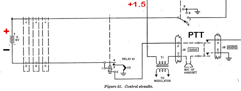
When the handset PTT switch is closed relay K1 relay will activate and supply minus - 6 volts filament power to the transmitter tube V3.
Q. Why all this fuss about the power switch?
Ans. Most of the problems that occur in the PRC-10 are associated with missing voltages to circuits.
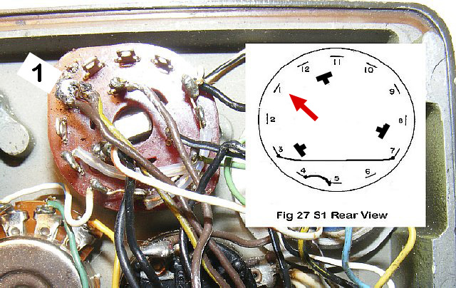
POWER switch S1 and Figure 27 from the manual for comparison . Insulated wire jumpers are on the switch from terminals 3 to and a bare wire jumper from 4 to 5. Locate Terminal 1 for orientation.
Voltage
Checks 
Some
quick voltage checks.
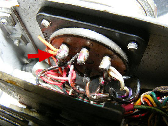
Rear
Power Connector.
Be careful when checking voltages on the rear chassis connector one slip of the probe and you can short out voltages between terminals.
Its
easier to check voltages on the chassis.
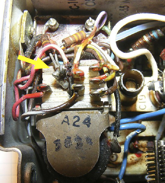
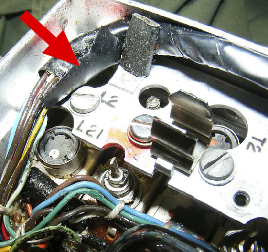
Yellow
arrow points to terminal 6
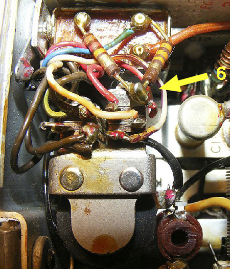
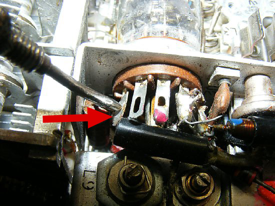
The
6 volt Push to Talk relay switches several voltages. Figuring out the
terminal numbers can be confusing.
Use Terminal 6 to to help identify the other terminals.
Terminal 6 has two resistors connected to it. ( Resistor R40 and R41 on
the schematic)
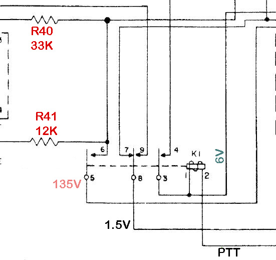
Terminal 5 supplies High Voltage to
terminal 6 when Push to Talk is keyed and the relay contacts close.
Q. Why all this fuss about the Push
to Talk relay K1.
Ans. On the
PRC-10 transceiver K1 is a open relay. Contacts may need to be cleaned
or adjusted. BTW the PRC-10A has a "sealed" relay.

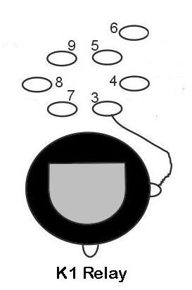
Voltages with reference to chassis ground.
During
Receive Number 8 contacts to number 7.
During
Transmit(PTT) the relay coil is powered and the contacts close and then:
Number
3 contacts number 4. Number 5 contacts number
6. Number 8 switches from 7 (receive) to
number 9 (transmit).
Using your meter you can carefully
probe the top terminals connectors of the relay. CAUTION:
High Voltage 135 volts is present. Not only can it shock the
piss out of you but if you are not careful with the probe you might short
the HV (135 volts) to one of the low voltage filament busses (1.5 or 6V)
and damage tubes by burning out the filaments. There are other ways to
make quick voltage checks shown below.
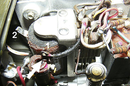
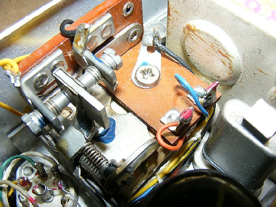
A different relay configuration.
R40 and R41 resistors on the other side. (Contacts 5 and 6)
Evidently there were several different relay configurations used during manufacture. Photo above has the High Voltage contacts 5 and 6 on the left side. Note the two resistors attached to terminal 6.
K1
Receive Transmit Relay
A quick check for
6 volts is Terminal 1 (coil winding) on the relay.
During receive 6 volts will be present on both coil terminals of the relay.
During transmit the PTT switch grounds terminal 2 but 6 volts will still
be present on terminal 1. Note the
loose wire on C12 - I fixed that.
NOTE: During trouble shooting you can always activate the RT relay manually by pressing on the top.

Clean contacts with a small thin
piece of cardboard soaked with Deoxit. Run the "wet" cardboard
back and forth between the contacts. Keep the Deoxit out of your eyes
and wash hands after using. "Deoxit cleans the contacts and "Chemically
improves connections".
Google DeoxIT.

1.5 Volt voltage check
A handy check for 1.5 volts is the switch terminal S2 on the rear of the squelch pot. This switch on the rear of the squelch pot disables the squelch by turning squelch knob all the way CCW until you hear the switch click which activates the switch and opens the filament circuit to the squelch tube V11.
1.5 volts should be present at the rear of the squelch knob on the switch terminal anytime the main Power Switch is positioned to ON or CAL
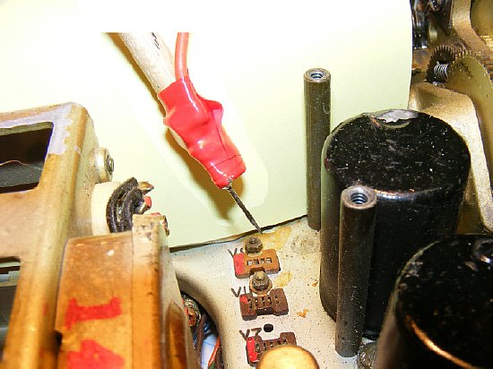
Transmitter
tube 5A6
A
quick check of the high voltage (135V ) can be made on pin 1 of the 5A6.
You must be in transmit using PTT.
67 volts plus or 1/2 of your B plus supply should be present on the coil terminals of the squelch relay. (Red and blue wires)
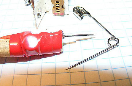
A handy socket pin probe for checking miniature tube socket voltages above the chassis when the minature tube has been pulled.
Q. Ever wonder what the voltage is on an insulated wire and don't want to disconnect it?
Ans. Find out using the k4che safety pin probe. Turn the power off then stick the probe through the insulation. Turn power on. Keep one hand in your pocket.
A quick check of basic socket voltages without the tube can be made with the Safety Pin probe.
Several different ways to check activity and frequency
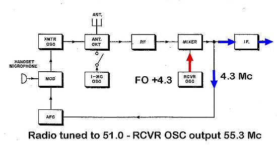
Symptom:
No receive or transmit. A very common problem with the PRC-10 series is
failure of the receiver oscillator circuit which is used for both receive
and transmit.
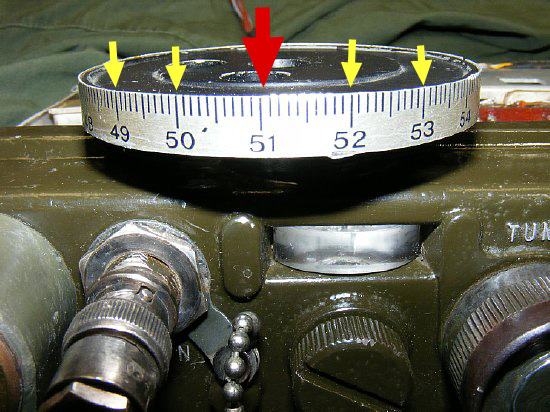
The
receiver oscillator operates at a frequency of 4.3 Mc above the
PRC-10 "Dial" frequency. When the PRC-10 radio is tuned to 51.0
the oscillator should be on 55.3 Mc.

When you tune the dial to 51.0 the RCVR OSC frequency should be 55.3. The RCVR OSC is used for both receive and transmit.
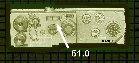
An
easy way to check for RCVR OSC activity and frequency is to tune
the PRC-10 to a specific frequency (example above is 51.0) and then
listen on a near by receiver at 4.3 Mcs above your PRC-10 dial frequency.
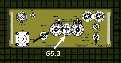
For example tune the PRC-10 to 51.0 Mc.
Then
tune a near by receiver to 55.3. ( 51.0 + 4.3 = 55.3
Mc)
During
your test tune the main tuning knob on PRC-10 above and below 51.0 in
case there is a large error in the calibration of the PRC-10 dial.
Listen on a near by receiver tuned to 4.3 Mc above the PRC-10 "Dial" frequency to confirm PRC-10 RCVR OSC operation and frequency. More info below.
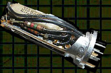
The RCVR OSC module is located near the rear of the set.
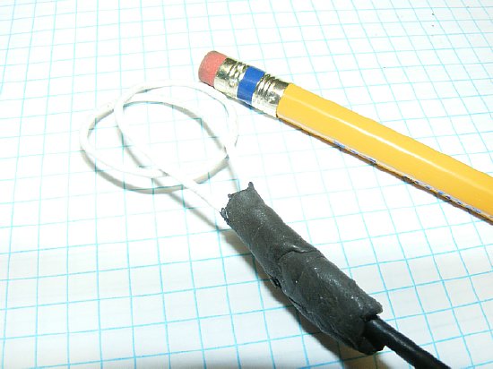
A
simple useful tool. Two (2) loop at the end of RG-58 or RG-158 coax cable
with a BNC termination.
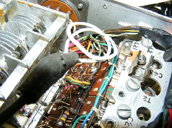
Remove the XMIT OSC tube V3 to allow access to the module area. Place the "Snoop Loop near the RCVR OSC module and use your frequency counter. More on use of the frequency counter below.
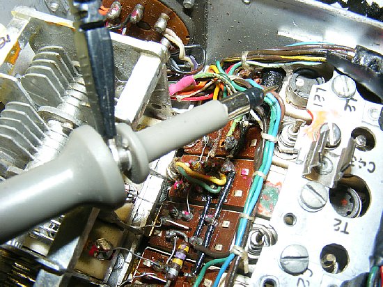
Another quick way is to just put your scope on the lowest voltage setting and place your probe (X1) near the oscillator. The high sensitivity amplifier of the scope using the probe as an antenna will pick up the oscillator.
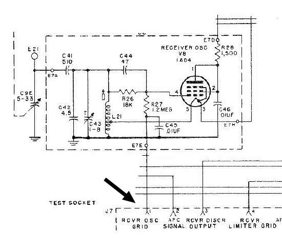
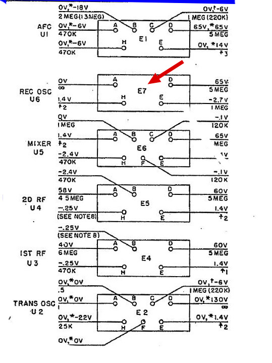
Reference chapter 3 Checking Receiver Oscillator V8 -Connect a VTVM (DVM) across terminal 1 of J7 and ground. If V8 is oscillating, the bias voltage will be about -3 (minus 3) volts; if V8 is not oscillating then bias voltage will be zero. Using a standard analog meter won't work as it will load the voltage down and the bias indication will be hard to detect.
PLEASE NOTE: I also tried using a scope probe and frequency counter on Test Socket J7 Pin 1 and depending on the sensitivity of your frequency counter you can measure the RCVR OSC frequency and as a bonus when you transmit it will give you transmit frequency. There is free lunch after all. On your scope you should see 20-40 mV peak to peak.
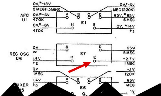
You
can also access the test socket pin 1 voltage on the REC OSC module at
pin E. same same G.I.
For minute receiver dial errors you can loosen the dial and move it to the correct indication. I usually just make sure the 6 meter dial coverage 50-54 is correct on the PRC-10 and not worry about the lower ranges. On the PRC-8 ham band ops adjust make minor corrections on the dial l for best accuracy on the high range and for the PRC-9 do just the opposite and adjust for the lower range.
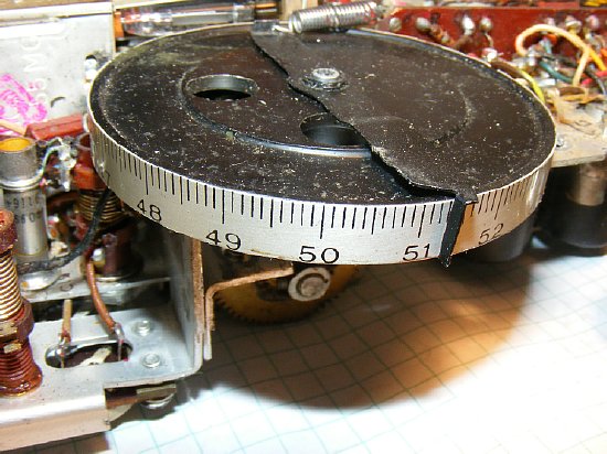
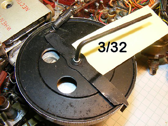
Its a nice dial. The pointer is press fitted and the hex screw assembly holds everything in place.
Note that the dial is not a logarithmic scale - there are 10 divisions for each Mc of coverage and the spacing remains the same. PFM.
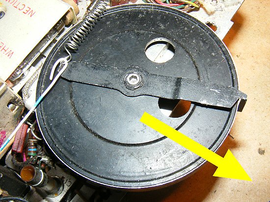
TIP: When reassembling the radio after front panel removal hold the spring as shown above to move the pointer out of the way.
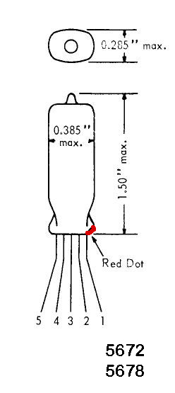
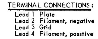
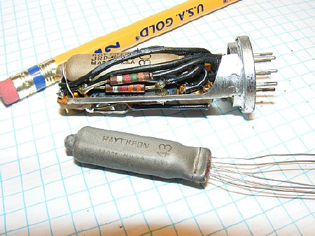
Pin diagram of the 5672 and 5678 miniature tubes used extensively in the PRC-10.

Raytheon
developed the miniature tube during WWII for use in proximity fuzes. A
proximity fuze is used to detonate an explosive device automatically when
the distance to the target becomes smaller than a predetermined value.
A good portion of our countries electronics industry during WWII was dedicated
to manufacturing these proximity fuzes and the fuze was a major contribution
to our war effort. Google Proximity Fuze.
"These tiny tubes were manufactured
to meet the stringent MIL-E-1 specification for reliability and designed
for long service life under conditions of severe shock, vibration (up
to 20,000G), high temperature and high altitude. These tubes were some
of the most meticulously built and most rigorously tested of all tubes,
as their main intended use was extreme military applications. Theyre
exceedingly tough and will easily withstand a drop test from a height
of three to four feet onto a tiled or concrete floor without breaking.
"
The above quoted from "effectrode web site"

http://www.effectrode.com/signal-tubes/subminiature-tubes/
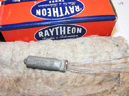
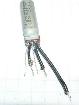
The tubes are manufactured with long leads for direct wiring without sockets and when utilized with sockets in the PRC-10 the leads are trimmed.
Info:
The RS-6 uses the miniature tubes that are hard wired and soldered in
place.
The PRC-6 uses similar tubes and has several 5672, 5676, and 5678 tubes on board.
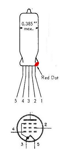
When inserting the miniature tube into the socket match the red dot on the tube with the red dot on the socket. Pin 1 is nearest the red dot.
CAUTION: Inserting a tube backwards could result in filament failure.

When aligning the tube pins match the red marking of the tube base to the socket. Pin 1 is next to the Red area.
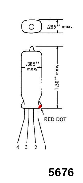
The 5676 tube has only four pins and is used in the modulator V2 and the 1 Mc Calibration Osc V9.
CLICK
to enlarge
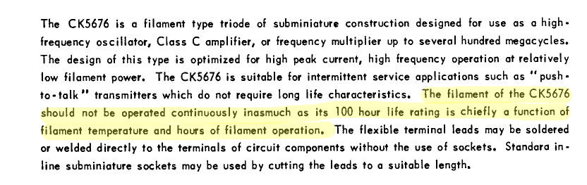
Bad News: The 5676 miniature
tube filament has a 100 hour life. Good News: In the PRC-10 the
5676 is only used in intermittent service on Transmit when the filaments
are keyed by the TR relay. It is also used in the 1 Mc CAL OSC. There
are a total of two (2) 5676 tubes in the PRC-10.
During transmitter failure due to a faulty 5676 you can pull the tube from the 1 Mc CAL OSC.
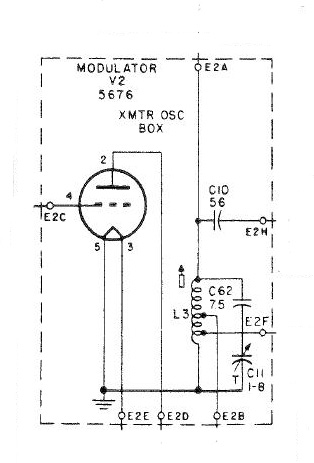
Modulator schematic. Note that on the schematic that the tube socket has no pin 1.
The 5676 tube has 4 pins.
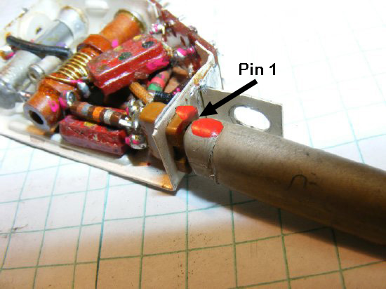
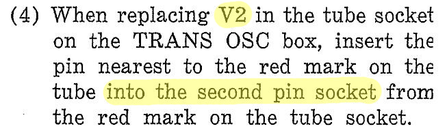
Instructions for use of the 5676 on sockets that have not been modified for 4 pins. See next photo.
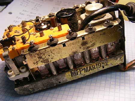
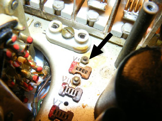
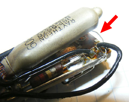
Transmit oscillator module (white arrow). Look carefully note that pin 1 of the 5676 socket is missing and that there are only 4 pins remaining. On some of the older sets the socket will have 5 pins and you must skip the first pin near the red dot.

This socket has been modified for use with the 4 pin 5676 tube.
V9 the 1 MC CAL OSC socket with pin 1 modified and only 4 pins remaining.
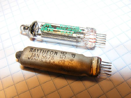
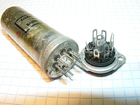
A comparison between shielded (5678) and non-shielded (5672)miniature tubes. The shield is "sprayed" on.
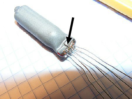
Its is easy to spot the connection between the shield and pin 3.

Lead #3 is connected to the shield.

READ
THIS Chapter 4 information.
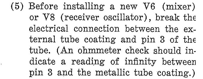
Another example of the shield connection. The shield connection enters the glass envelope and is connected to pin 3 internally.
There
is a CAUTION printed on the tube cover cover for the modules using the
5678 and 1AD4 tubes concerning the shield connection.
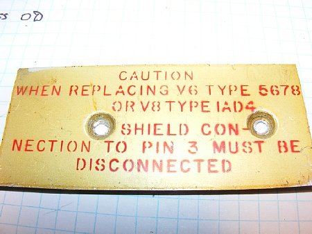
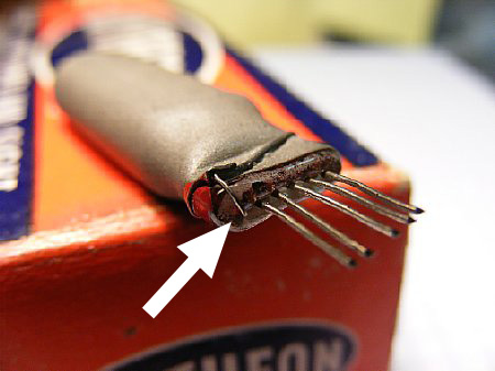
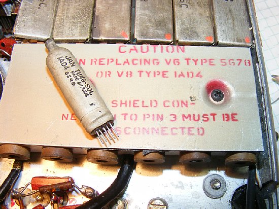
Module tube cover warning label.
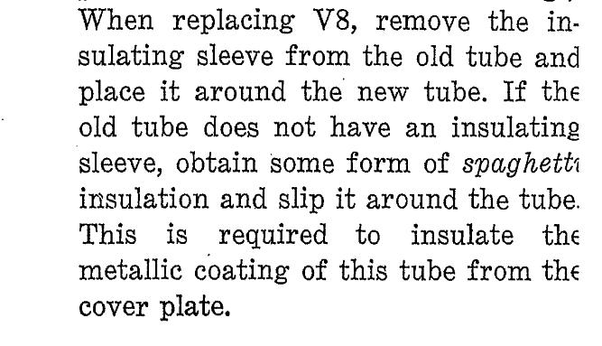
V8 is the Receiver Oscillator and in this case they want the shield in place but it must be insulated. You can use plastic tape.
The shield is connected to pin
3. Accidentally shorting pin 3 to ground will render the receiver OSC
inop and may cause damage to the 1.5 volt power supply.
Got a intermittent
receiver oscillator and varying 1.5 voltage buss? Then: CHECK
the insulation on V8.
Typical
miniature Filament Leads for the PRC-10 are numbered 3 and 5.
PRC-10
tube filament resistance checks.
WARNING:
DO NOT use a analog meter on the low ohms setting (X1) this may burn out
the filament of the tube being tested. Use a higher resistance setting
or better yet use a Digital Meter.
5672 6-7 ohms Pins 3 and 5
5678 6-7 ohms Pins 3 and 5
5676 7-8 ohms Pins 2 and 4 (5676 only has 4 pins)
1AD4 4 ohms Pins 3 and 5
5A6 3-4 ohms between pins 4 and 5 Note: The 5A6 has a center tap on the filament at pin 9 that is not used.
When testing
the filaments on the sealed IF modules use a tube socket to make positive
contact with pins 3 and 6.
NOTE:
The PRC-10 has sealed modules but you can unsolder the cover to have access.
Photos and information of the process can be seen later on this page.
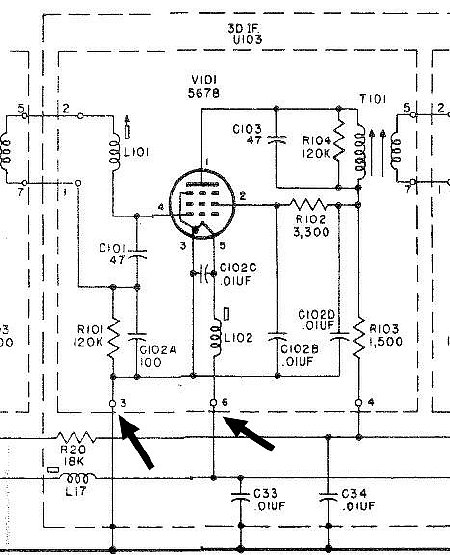
Pins 3 and 6 are the filament connections to the sealed plug in module. Note that the actual tube filament pins are 3 and 5..
I spent 20 minutes one night trying to figure out why all of my filaments were not checking out on the IF modules because I was checking pin 3 and 5 the actual tube filament pin numbers. Do not use the X1 position on a analog meter - use a higher position or better yet use a DVM.
ON "most" radios E1B is connected to terminal 2 of the test socket J7 which makes it easier to access but I would check this before doing any other measurements
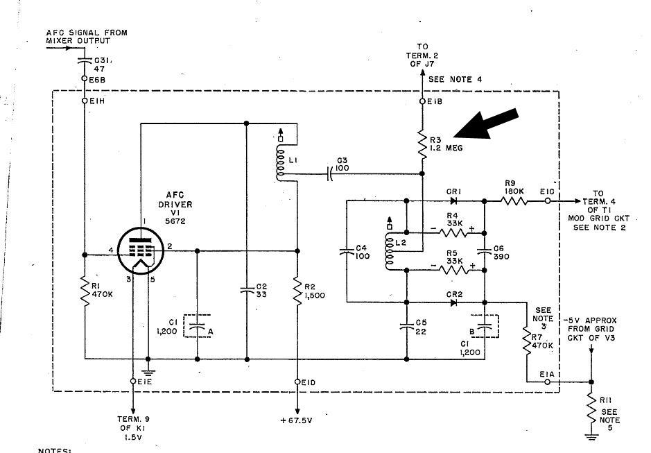
NOTE: The low voltages measured during our bench testing (6 to 7 volts ) vs. the 15 volts stated in the manual is probably due to resistor R3 which feeds E1B test point changing its value. R3 is a 1.2 Meg ohm.
More info below.

AFC Driver Ops Check
Transmitter way off frequency? Do the AFC Driver test.
But it is important to note that the voltage mentioned of 15 volts in paragraph b. above may be considerably lower due to the value of R3 changing due to age. Typical voltages measured on several sets here in our "Operations Center" was around 7-8 volts. Schematic below.
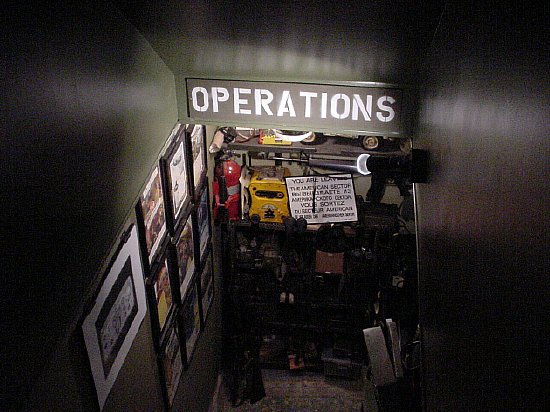
Entrance to the "Operations Center."
CLICK
to enlarge
During
the AFC voltage check expect lower voltages as R3 value as changed due
to age.
Handy Items
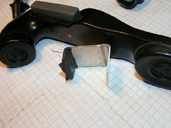
Its
hard holding a probe and using the PTT when making voltage measurements
on the transmitter. Fabricate a PTT clamp - put rubber tape over the end
of the clamp to protect the rubber on the H-33.
"Improvise
- Adapt - Overcome"

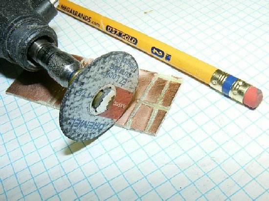
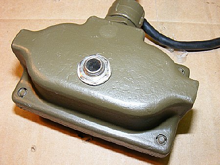
A 'breakout" panel for the H-33 handset connector (U-77/U) comes in handy. The panel was made using a Dremel tool on printed circuit board material. Label with a Brother "P Touch" label printer.
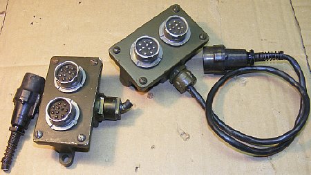
An audio splitter with parts obtained from Fair Radio. The connectors were all ready wired so all you need to do is add the single radio cable. Since you are splitting the audio there will be some loss when using two audio accessories such as H-33 handset but you can turn up the volume. The other connector comes in handy when demonstrating the radio and using a battery power audio amplifier.
A standard 1/4 inch phone jack was added.
Q.
Can I used an external speaker on the PRC-10.
Ans. Yes but you won't hear much as the output is at the millawatt level. Use an external amplifier.
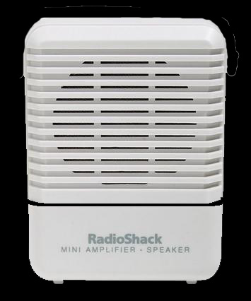
A great piece of test equipment Radio Shack 277-1008. But they are now gone. Cheep. Often seen on ePay. So sorrie G.I.
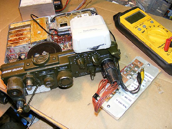
Its hard working on the receiver and holding the H-33 handset to your ear to listen to the audio. Shown above is a battery powered external amplifier (Radio Shack 277-1008) attached to the connector "breakout" panel.
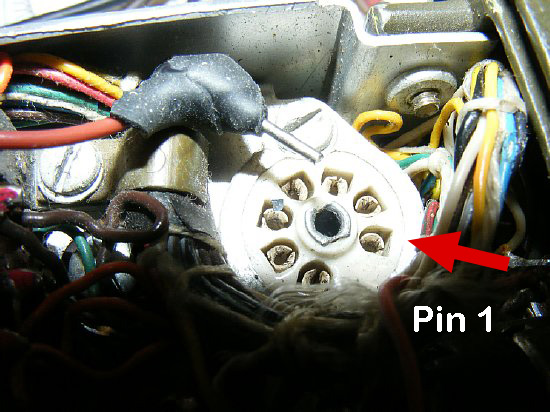
Paper clip test pin for the J7 Test Socket.
The "medium" size paper clip diameter fits the test socket pins. Note the location of Pin 1 on the test socket. Pin numbers run counter clock wise when viewing from the top.
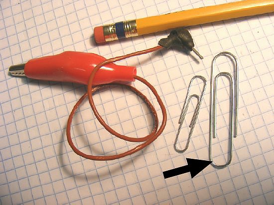
Cut off a short length of a medium size paper clip and use it as a pin which fits the test socket when inserted. The smaller paper clip wire is too thin. Fabricate a test lead but keep the actual pin portion short in length so that it can be inserted in the test socket and then the radio can be turned over on the bench for service without bending the pin.
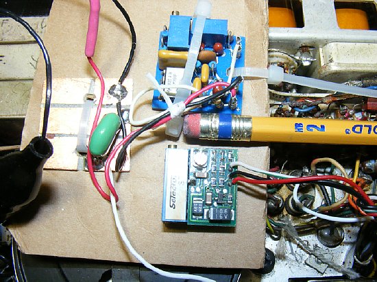
Several
PL boards were evaluated. Smaller is better. Both of the boards shown
above use a 10 turn precision variable resistor to set the tone frequency.
The bottom board is a Selectone ST-140 which is no longer made but appears
on ePay.
Other
board options discussed below.
Just
think you can be the only one at Dayton with a PRC-10 with "New Squelch".
But you may be the only one there with a PRC-10.

Terminal
4 of transformer T1 provides an excellent input for the tone and is convenient.
Adjust
your PL board tone voltage level at terminal 4 at .3 (point 3) volts peak
to peak. Or just adjust the tone level until proper "New Squelch'
action occurs on a near by radio. The deviation level desired is 3 Kcs.

Com-Spec makes
a miniature board SS-64 for encode only and tones are selected by a dip
switch. Set tone 5Z which is 151.4 and that works for most radios as it
is only 1.4 cycles off of the New Squelch tone frequency of 150 cycles.
During very weak signal ops the 1.4 cycle error may cause some squelch
problems but for most rallies and hamfests it should work OK. Take a walk
on the wild side and do the mod. BTW Com-Spec bought Selectone
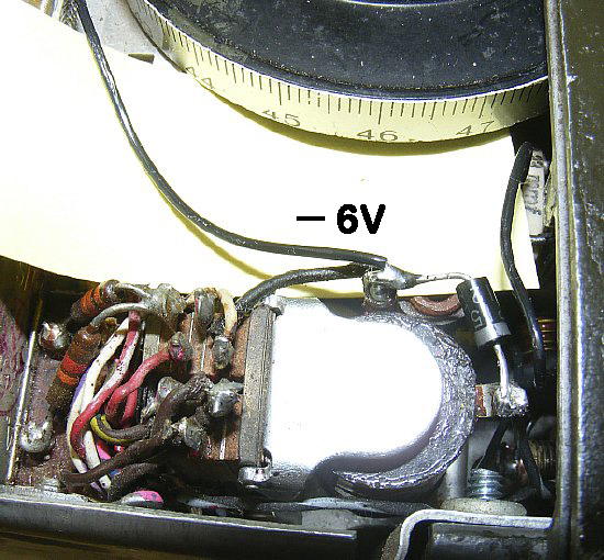
Power
for the board is obtained by using the - 6 volts accessible
on the relay terminal. Note the diode soldered in place to eliminate inductive
spikes which may damage the PL circuit IC when the relay is keyed. Ground
the red (positive) lead of the PL board to the chassis. The board
is not physically connected to the chassis so it will not know the difference.
Confused? Then go back to the 6 Volt power section.
Photo above the PL board is powered all the time. Photo below the board will be powered when PTT is activated. Why the different wiring? Some PL boards take a brief pause before output when power is first applied.
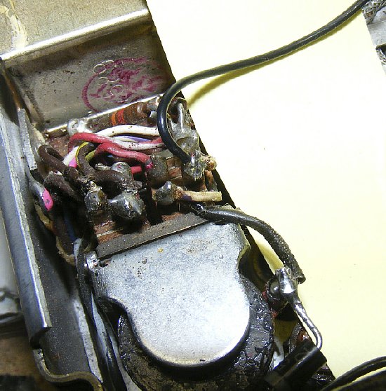
Photo above PL board is powered by Terminal 4 of the relay. The 6 volts is switched by the PTT. Go back and review the relay diagram.
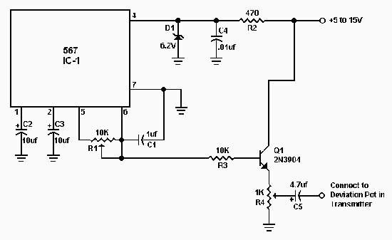
N1HFX photo
Project: Take a 567 IC and build the above circuit. Since you are dealing with a low frequency circuit the parts layout is not critical and you can build it to fit the space available in the PRC-10 chassis.
http://www.rason.org/Projects/decoder/decoder.htm
http://www.rollanet.org/~rrars/tech_files/pl_tone_ckt.pdf
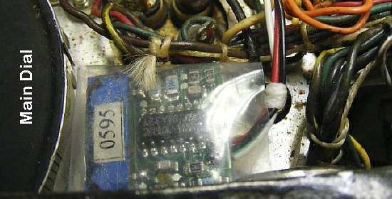
The Selectone ST-140
board is insulated with a plastic sleeve and mounted in the area near
the main dial and transformer audio transformer T1. Double stick tape
was utilized.
NOTE: A new procedure is published in this section that is not published in the manual. This procedure allows you to "zero beat" a station on a odd ball frequency such as 51.625 Mc.
The calibration oscillators produce markers at every 1 Mc point. Which is perfect for most military radio collectors which use the frequency of 51.0.
Q. Why all the fuss about the calibration oscillators
Ans. Since the PRC-10 frequency control is a variable tune system it helps if you can calibrate the dial. The unofficial FM frequency used by most military collectors is 51.0 and the PRC-10 is easily calibrated to that frequency and obtain transmitter accuracy of plus or minus 5 Kc.
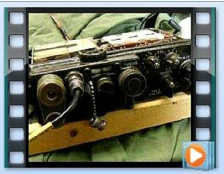
CLICK here for Calibration Demonstration Video.
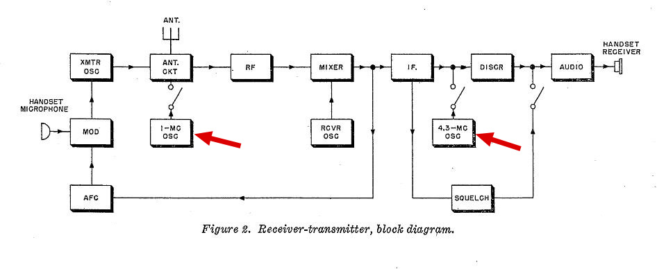
CLICK
to enlarge
The calibration circuit consists of two oscillators a 1 Mc and a 4.3 Mc. The 1 Mc OSC signal goes through most of the front end stages of the receiver. The output of the 4.3 Mc oscillator is injected into the discriminator where it beats against the IF frequency produced as a result of the mixing of the receiver oscillator with a harmonic of the 1 Mc oscillator. Its PFM and the best part is it gives incredible accuracy depending on the skill of the operator. Plenty easy G.I. to get on 51.0 with good accuracy.

You can easily confirm the 4.3 and 1 Mc oscillator operation. Connect a short piece of wire (several feet) to the antenna terminal of a near by receiver - place the other end of the wire in the oscillator section. Don't have a 1 Mc receiver? Then use a AM Broadcast set.
Zero Beat Instructions: (Handy when the other station is not on an even 1 Megacycle frequency.
Please NOTE: This procedure is not in the manual.
a.
Have the other station transmit a carrier without audio. If possible no
PL tone (New Squelch Off)
(The
other station has to be on a frequency that is not an even megacycle.
Example: 51.625)
b.
Tune in the other stations carrier for max quieting on the PRC-10.
c. Position the PRC-10 Power switch to CAL and have station continue to transmit a carrier.
c, Tune for Zero Beat and release the CAL switch.
d. You are now on the other stations frequency.
| Squelch Circuit |
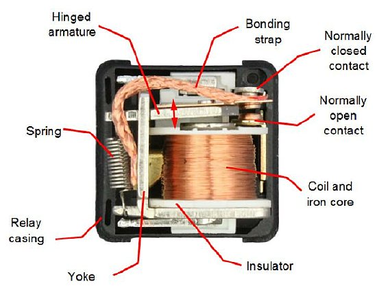
A little review of relay construction. The normally closed contact stays closed due to spring action until the coil is powered and over rides the spring tension and then the normally open contact closes.
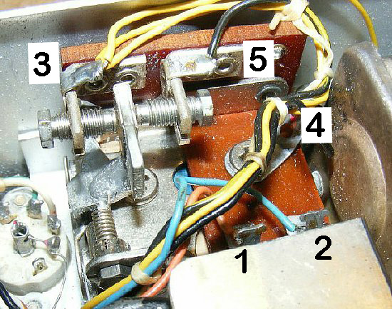
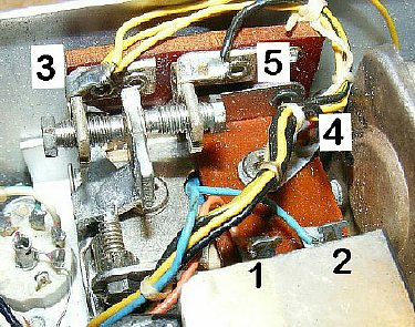
Squelch
Relay Schematic Terminals
Terminals
4 is connected to the center armature and is grounded to the chassis.
The spring tension keeps the armature connected to terminal 5. Terminal
3 is low level audio. When the relay is powered terminal 4 connects to
terminal 3 and mutes the audio providing a simple squelch action.
High
Voltage is present on terminals 1 and 2 which supply voltage to
the coil.
CLICK to enlarge
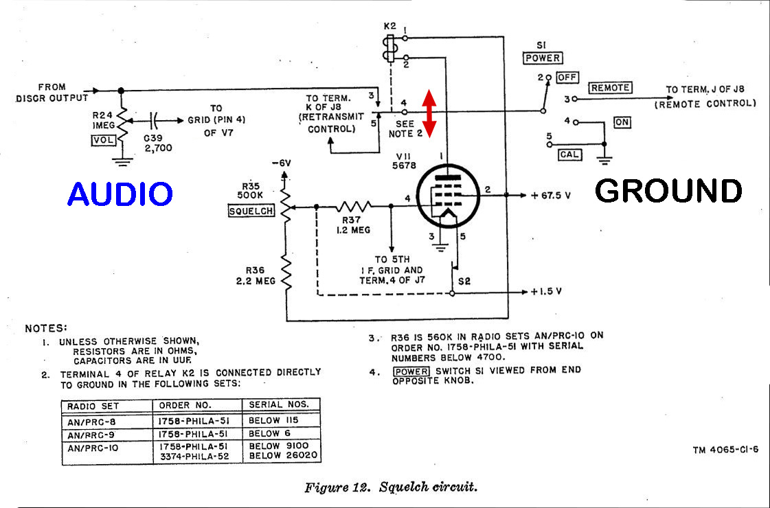
Fairly simple squelch circuit. The low level AUDIO from the discriminator is grounded or ungrounded for squelch action.
Note that armature terminal 4 of the relay is grounded when the set is turned ON or is in CAL. When the relay is powered the armature terminal 4 connects to terminal 3 and the audio input to the grid of the amplifier V7 is grounded.

Squelch Action occurs when the armature of the relay is positioned either
left or right. Right is UNSQUELCHED. Left is SQUELCHED.
Manual
Check of Squelch Relay: When trouble shooting you can make a quick check
of audio squelch action. Take a plastic probe and using very light pressure
you can move the relay armature back and forth - if the relay is powered
you can easily over power the pull of the coil. Movement to the right
should result in receiver noise.
Watch out for high voltage on the bottom terminals.
Scope
check of audio. You should see low level audio on terminal 3 (yellow wires).
Audio should disappear when relay is powered and terminal 3 is grounded.
Q.
Why all this fuss about the squelch relay?
Ans.
The relay is an old style open construction and can be a mechanical/electrical
problem. The relay assembly is subject to dirt and adjustment problems.
Very sensitive. Later the PRC-10A went to "sealed" relays
for squelch and RT.
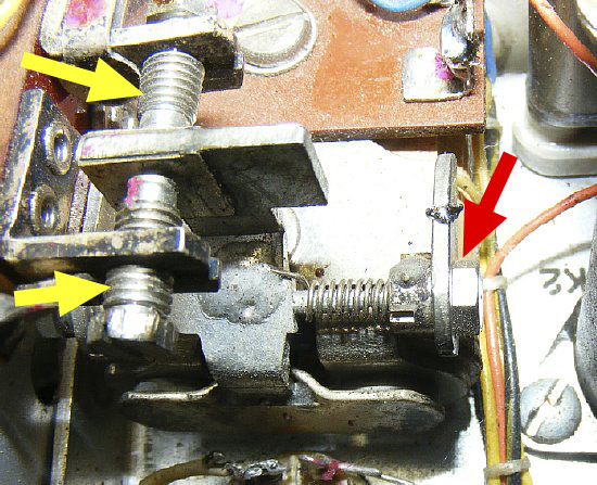
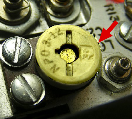
Adjustment
screw (Red Arrow) for spring "bias" adjustment of the armature.
Yellow arrow point to the contact spacing adjustments.
Best advice is try and leave the adjustment screws alone but if the set
has been "ham hacked" then adjustments may be necessary
Clean contacts with a small thin
piece of cardboard soaked with Deoxit. Run the cardboard back and forth
between the contacts. Keep the Deoxit out of your eyes and wash hands
after using. Deoxit cleans the contacts and "Chemically improves
connections".
Google Deoxit.
SQUELCH CHECK
| Squelch Knob Position | Relay Action | Result |
| Turn Full CW | Relay Powered | no noise |
| Turn CCW 1/2 to 2/3 turn approximate | Relay Unpowered | noise |
| Full CCW switch clicks | Squelch disabled | noise |
Relay powered- contact is made between armature
terminal 4 and relay contact terminal 3.
Relay unpowered - Contact is made between armature
terminal 4 and relay contact 5.
Turning the Squelch Knob Full
CCW until the switch mounted on the rear of the squelch control clicks
results in the opening of S2 (switch) -The 1.5 voltage is removed from
the filament of V11. Then no squelchee.
Squelch Relay Voltage and Resistance
Checks.
Power Switch must be ON. Minus lead of your meter is to chassis ground.
Terminal 1 - Voltage 60 to 70 volts volts (one half of your B plus supply).
Terminal
2 - Voltage with squelch Knob full CW should be approximately 30 volts.
Then turn the Squelch knob slowly CCW and monitor voltage on terminal
2. The voltage will slowly increase to approximately
60-70 volts at which time the relay becomes unpowered and the spring returns
the armature (relay makes a slight mechanical click) and receiver noise
should be heard . clicky - clicky
Squelch Relay Resistance Check
REMOVE Power from the set.
Isolate
the relay from the squelch circuit by removing one of the wires from either
either terminal 1 or 2.
The resistance
of the relay coil between terminals 1 and 2 should be approximately 16K
ohms.
Note: Most low voltage relay coils will have a very low resistance. This
relay is a high voltage "plate" relay and the coil will measure
much higher and in this case approximately 16K.
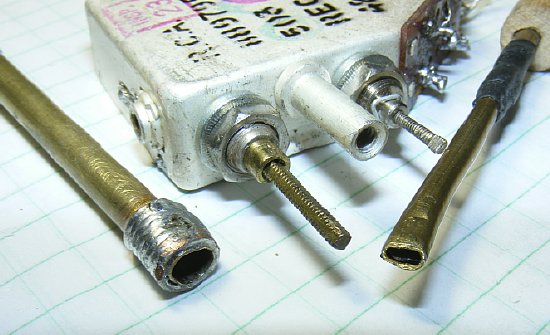
You can't play if you don't have the right toys. Make your own alignment tools out of brass tubing.
More info an be found in:
PRC-10 Part 1
NOTE:
Do a Complete transmitter Alignment if the set has been ham hacked.
Read the alignment section (Ch 5) of the manual instructions first to
get details then to make things simpler use the steps below. Some of the
steps are different from the manual.
Best
Bet: When touching up the transmitter frequency and power for use on 51.0
Mcs just do the High End Alignment below.
rev3
Turn L3 CW to bottom position.
Turn C11 to position stem flush with the bottom bracket (stem all the way in).
Adjust C17 to minimum capacitance with the arrow towards side away from mounting screws.
Note the small arrow on C17.
Minimum is when the arrow points away from the mounting screws.
Connect DVM minus lead to the R13-R11 Junction and positive to pin 5 (AFC) of Test socket.
Set dial to 39.0 Mc (low end alignment) using CAL position.
Adjust L3 for "correct" zero voltage on DVM..
Adjust
L9 for max power into 50 ohm load then readjust L3 for "correct" zero
on DVM.
-
- - - - - - - - - - - - - High End Alignment - - - - - - - - - -
Set Dial to 54.0 (high end alignment) and calibrate using CAL position.
Adjust C11 for "correct" zero on DVM.
Adjust C20 for max power into 50 ohm load.
Readjust C11 for "correct" zero voltage.
Disconnect 50 ohm load from BNC aux connector.
Adjust C17 for "correct zero" or as close as you can get it.
Then: CALibrate receiver to 51.0 using CAL position. Do an accurate "zero beat" and then transmit and measure the frequency of the transmitter with a frequency counter. Repeat CAL procedure and measure transmit frequency several times to determine average error.
IMPORTANT: In the
event the transmitter is off frequency by a small amount adjust readjust
C11 slightly and if that does not work read the Frequency TIP below.
Often due to the aging of the components in the AFC module the transmit
frequency may be off 20 -30 kcs from the receiver frequency as the "correct"
zero reading may be in error. In this case C11 will not correct the problem.
See OFF FREQUENCY
TIP below. Note: This transmitter "OFF FREQUENCY TIP" correction
procedure is not in the manual.
OFF
Frequency TIP: Coil L2 on the AFC module can be used to correct small
errors in the transmit frequency.
The "Correct Zero" reading
used during the alignment steps may be slightly in error due to aging
of components such as CR1 and CR2 as well as R4 and R5 in the AFC module.
See Schematic.
After calibrating using the CAL position and placing the set on exactly on 51.0. Measure frequency transmit frequency and if the transmitter is still off frequency by more than 5 kcs then L2 on the AFC module can be adjusted slightly. CW of L2 raises the frequency - - CCW lowers the frequency. Turn in very small increments such as 1/8 turn etc. Turns more than 1/2 a turn to correct the frequency will be rare. The target is to be on frequency within 5 kcs or better. After all has been done check the set on short and long antennas. Any unstable operation probably can be corrected with C17 the neutralization capacitor.
Click here for Abreviated check list for transmitter alignment.
Coil L2 on the AFC module is hidden in the rear corner of the set usually under a wiring bundle.

The powered iron core L2 on the AFC has aged and is very delicate. When adjusting the slug turn just a small amount at a time and check frequency. Fabricate a tuning tool. I prefer a tip fabricated from thin plastic.
The IF module cover can be unsoldered and removed for maintenance. When ordering a replacement 5678 tube make sure it is NOS with the long leads.

Use a high wattage soldering iron to melt the soldered seam at the base of the tube.
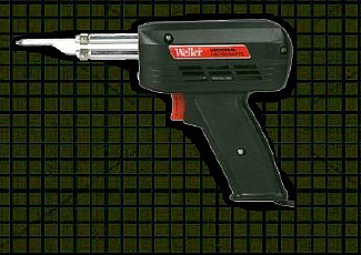
An excellent shop tool the Weller 260/200 catalog number D550PK. Great for "properly"soldering the coax braid on PL-259 connectors which no one seems to know how to do. ePay has plenty of the Weller 260 irons.
However since it is a Weller
it is subject to the "Weller Soldering Iron Magnetic Phenomenon"
an unsolved mystery.
http://k4che.com/WellerIrons/Wellerpage1.html
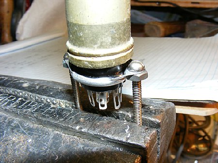
A 7 pin socket mounted on bolts holds the IF module during heating of the base to melt the solder. Move the tip of the iron all around the base and at first apply a little solder to conduct the heat from the iron. Wear gloves. Twist the upper housing slightly and then slowly pull the housing away from the base.
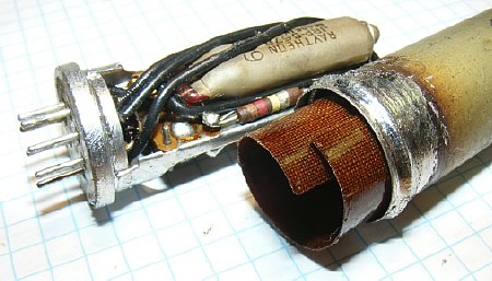
Wear gloves. When removing the module cover be careful and do not damage the insulation.
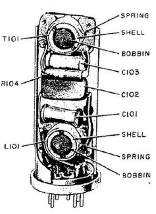
Using diagrams from the PRC-10A manual makes it is easy to identify parts and their location.


The
long leads of the 5678 are trimmed to length and insulated for proper
installation.
NOTE: L102 is a very small choke buried in the
base. You do not need to access it unless it is open and you have no filament
continuity.
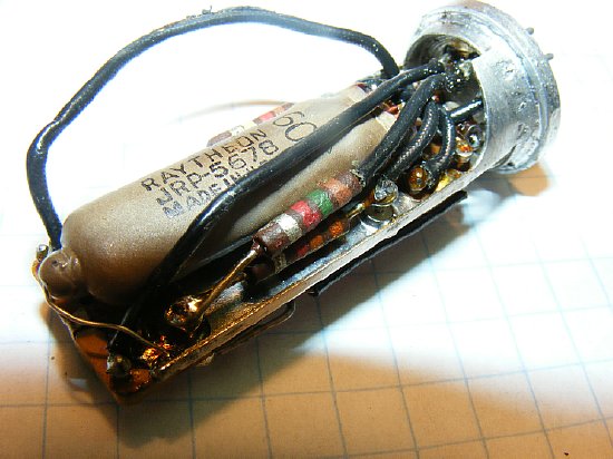
Some of the wiring can be moved for access to the tube.
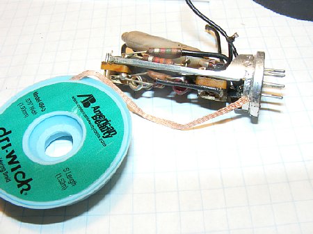
Use
solder wick on the tube lead connections to remove the solder before pulling
the wires free.
I prefer "dri-wick" 448 made by American
Beauty.
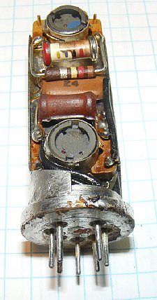
Its fairly easy to unsolder the tube leads. Leads 1 and 3 are on the other side.
The tube "clip" made of thin bare wire can be moved to free the top of the tube. Do not unsolder the clip.
After moving the tube clip made out of thin wire the tube can be positioned for better access.
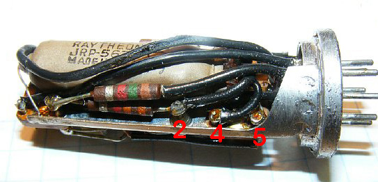
Tube lead connections. No arrows - take notes when unsoldering and make a drawing.
Use
the old tube as a guide for cutting the leads on the new tube. Reuse the
black insulation. Note:
Insulate the leads 3 and 5 just in case. Use insulation stripped from
junk box wire.
Improvise
- Adapt - Overcome
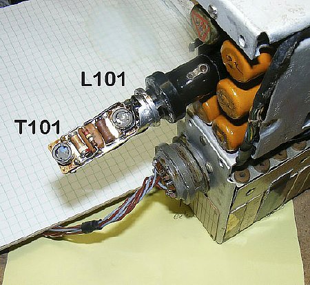
Use a tube socket extender and align the module while it is inserted into the set. T101 tuning was fairly sharp and you should not have to turn the powered iron slug more than a quarter of a turn to peak. L101 was fairly broad in tuning. Instead of throwing those IF modules that are inop in the junk box do a little repair work.
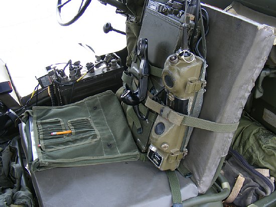
The
Prick 10 gets a lot of attention at military rallies etc. They are rare
and you don't see too many of the sets operational.Thousands were manufactured.
Pair it up with a PRC-6.
The
next section "PRC-10 Part 3"will be on the PRC-10A. A later
version of the PRC-10 radio with many improvements and some disadvantages.