Using the R-390A Below 500 Kcs
The R-390A can be used below 500 Kcs without any major modification.
Several
years ago Dr. Dallas Lankford published "The Hollow State Newsletter"
This newsletter was well written and contained many modifications and
alignment tips etc. for the R-390.
Someone published a compilation of the early articles 1-30 and it circulated throughout the Internet. It was in this compilation that I found Dr. Lankford's notes on using the R-390 below 500 Kcs.
"Hollow State Newsletter"
CLICK to enlarge
Click
to enlarge
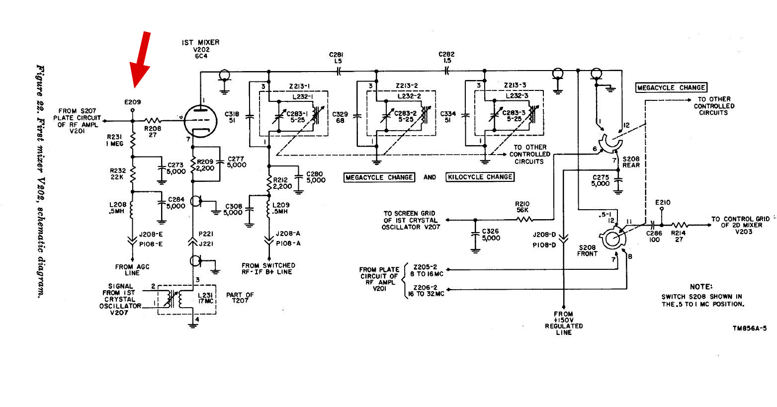
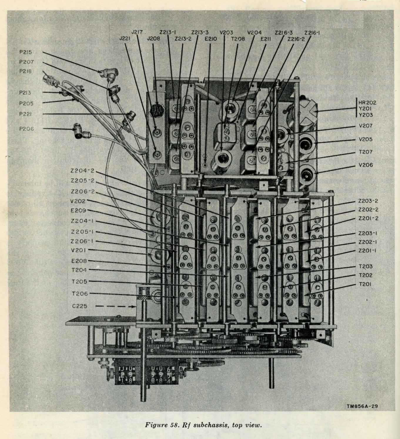
Dr. Lankford suggested using test point E209 on the RF chassis for antenna input and then tune the R-390A below the bottom of band 1 which is 500 kcs. Anyone that has played with the broadcast band has found that RF sensitivity rapidly drops off when you get 20-30 Kcs below 500 kcs.
Problem:
There is no RF input network for the R-390A below 500 Kcs. A matching
coil will help with overall RF sensitivity.
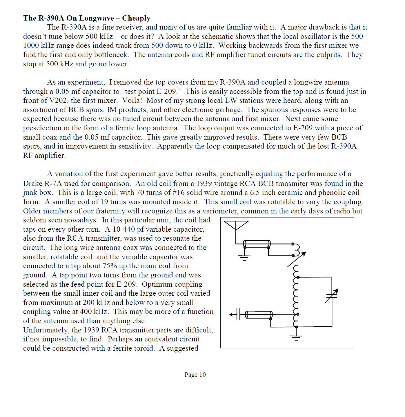
Solution: Build a matching network for a random wire antenna.
Click to enlarge.
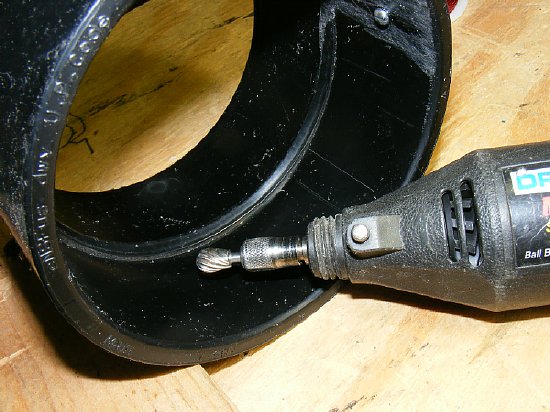
Test point E209 is easy to find as it is in between V201 andV202 on the RF chassis.
Experiment: Take a random wire antenna and couple through a .05 Cap (value not critical) - insert into the test point E209 and tune below 500 Kcs and listen for navigation beacons.
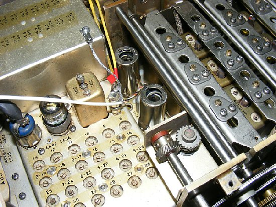
I used shielded wire for input to E209. Audio cable is fine or you can use coax such as RG-174. Not critical.
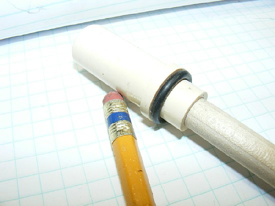
A simple clip and capacitor provide the input to E209 from the tuning coil.
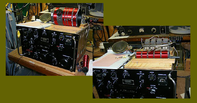
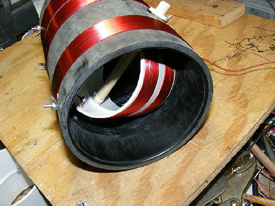
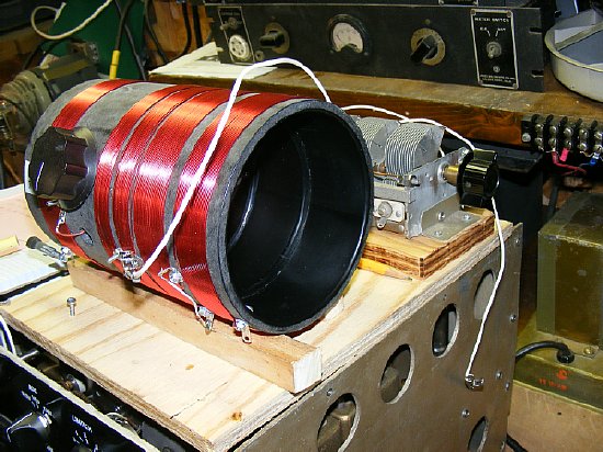
Above - R-390A receivers ready for reception below 500 kcs. Two different RF input antenna tuning coils are shown. On the left a variable tapped tuning variometer and on the right a tapped fix coil that is tuned with a ferrite rod.
On these pages I've posted suggestions on building a tapped tapped variometer coil and another tapped fixed coil that is tuned by inserting a ferrite rod. These coils will aid in matching your antenna to the input of the R-390A mixer stage via test point E209. ABS and PVC couplings from your local home supply store will be used and there are plenty of dealers on Epay that sell #20 enamel covered wire. (Must have enamel for insulation)
Videos LF reception using the R-390A and a antenna matching coil feeding mixer test point E209.
Millville NJ Airport Beacon 55 km. Variometer tuning.
Aberdeen Beacon 67 km away. Fixed coil varied with a ferrite rod used for tuning.
Two excellent sites below for Low Frequency Navigation Aid Identification.
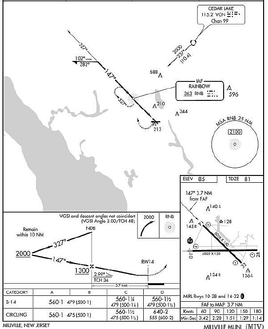
Millville RNB beacon is used for a "ADF" approach and also serves as a fix for navigation to the OM for an ILS approach.
A
variometer allow you to add or subtract inductance when you adjust the
inner coil. Its PFM. Additional taps give you plenty of range. Go to Lowe's
pick up some ABS or PVC couplings and cement- pick up some #20 wire on
ePay
When
the inner movable coil is lined up in phase with the outer coil it increases
the total coil assembly inductance and at 90 degrees the mutual
inductance reaches zero (all most) and the inner coil is neither adding
or subtracting from the overall total inductance of the coil. And if you
continue to rotate the inner coil past 90 degrees the total coil inductance
of the entire coil assembly decreases. So being able to rotate the coil
180 degrees you can adjust the "total" inductance of the entire
coil assembly by the amount of inductance of the inner coil. The changes
won't be exact due to coupling of the two coils etc.
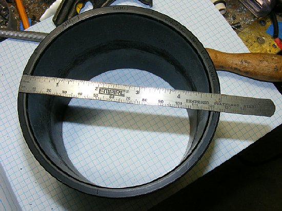
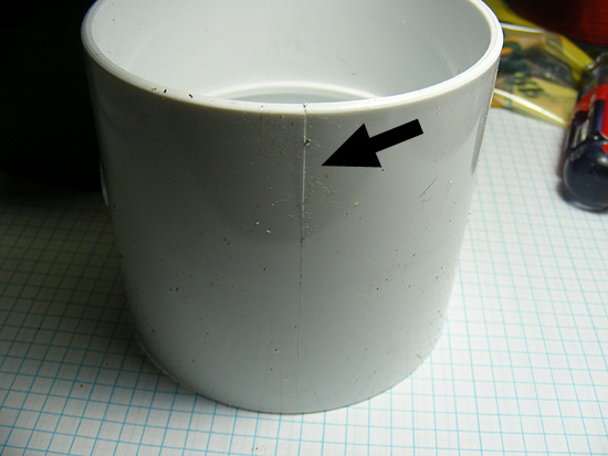
"Black" ABS Coupling was purchased at Lowe's from the irrigation section. A 5 inch OD ABS outer coil form and a smaller 3 1/2 inch PVC are used. There is thick wall ABS and thin wall ABS , shop around. The black ABS is very easy to glue and requires no prep other than a very light sanding.
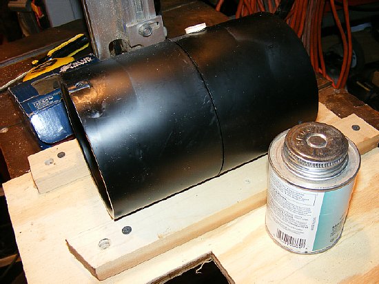
The couplings can be glued together using PVC cement. A wooden jig helps keep the two couplings aligned for gluing.
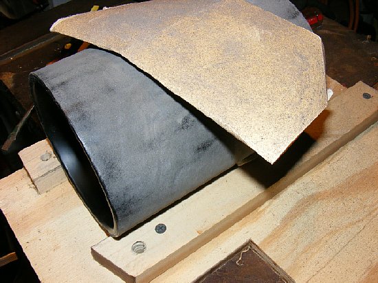
Sand the coil form to aid in winding. The rough surface will aid in keeping the turns in place and gives your coil form a nice stealth look.
Most couplings have a "stop ridge" in the center. Consider removing it to allow more clearance for the inner coil assembly to rotate.
![]()
Put the large coil
form aside and start on the smaller inner coil.
This will give you practice in winding and help determine the location of windings on the larger outer coil. This particular white 3 inch PVC coupling has an outer diameter of approximately 3 and 1/2 inches which is quiet a bit smaller than the inner diameter of the 5 inch ABS form that it will turn in. Keep in mind that the inner rotating coil form has to turn inside the outer form. The coupling shown above will have to be trimmed in length in order to allow 180 degree rotation inside the large 5 inch coil form.
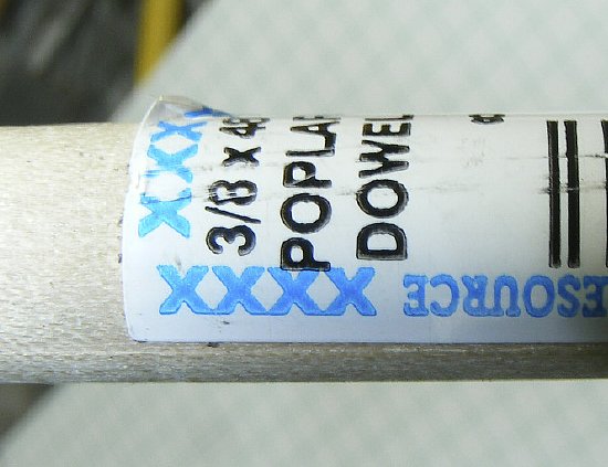
While you are at Lowe's or Home Depot etc. pick up a couple feet of 3/8 wooden dowel which will be used for the tuning shaft.
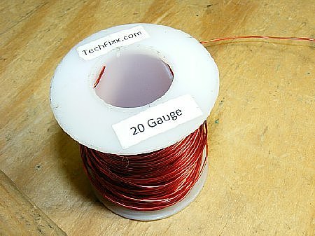
#20 enamel wire is my favorite size. Doesn't stretch too much and is pretty strong which is important during winding. Plenty of wire sellers on ePay.
Before sanding look for injection mold marks on the PVC this will help you to align the two (2) holes that you drill to insert the 3/8 inch wood dowel tuning shaft. This piece shown above had marks spaced 180 degrees apart. Perfect.

The inner coil PVC will have to be trimmed in length in order to be able to rotate 180 degrees inside the outer coil. Play with it.
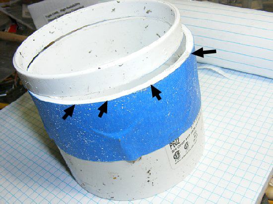
Use painters tape to mark the smaller coil prior to cutting. A hack saw makes a nice straight cut. I used a coil length of 2 and 1/2 inches for one coil but the clearance between coils was kind of close so I used 2 1/4 inches for the next coil and had better clearance.
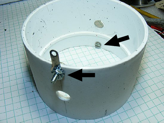
I used 4-40 hardware and a soldering lug for winding termination points on the form. Note the location. One lug is at the beginning and the other lug is at the end and 180 degrees apart. Flexible wire leads will be soldered to these point to connect to the outer coil.
The solder lugs make nice tap points for an alligator clip during tuning.
Circumference = Pi X Dia 5 inch coil (3.14) X 5 in) = 15.78 inches.
WINDING TIPs: Rig a vertical holding jig for your small reel of wire as the reel must be able to rotate freely as you pull wire from the reel - you will only pull off what you need. Feed the wire through the jaws of the vice but don't clamp the wire yet. Secure one end of the winding on your coil form. Take the coil form and walk across your shop and extend about 20-30 feet of wire and tighten the vice to temporary hold the wire while you wind your first turns. Hold the coil form with two hands and slowly rotate the coil and wind while you approach the vice - keep the wire taut as you wind. When you get to the vice which is temporary holding the wire then use with one hand to keep the coil from unwinding from the coil and use the other hand to loosen the vice so that you can meter out additional wire then close the vice again. When the coil has enough windings keep the wire taut and estimate where the wire enamel needs to be removed for a connection and then use a razor blade to accomplish same. Secure the end by wrapping the bare wire around the 4-40 bolt which was previously installed or insert the bare end in the PRE drilled holes. Its not Rocket Science - play with it. An alternate method is to get your wife to assist you - you will be amazed at how many winding techniques she can offer and how a simple process can be turned into a lengthy complicated task.
I love my CoPilot, she knows a lot of stuff
and likes to ride in the M151A1. When I was flying single pilot in Turboprops
she would come along on some of the trips and sit in the right seat and
make radio calls. Years ago she soloed at Travis AFB and is an excellent
Copilot plus she knows how to pick nice hotels.
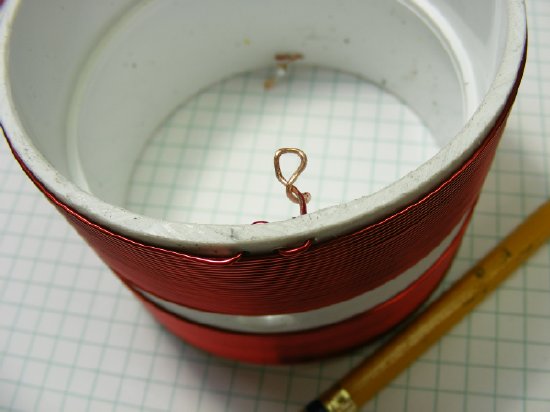
An alternate method of securing the wire ends is just feed the wire through a couple of holes and then form a soldering loop. But its easier to use the 4-40 hardware to secure the winding. Solder on several inches of "flexible" insulated wire on the end for connections to the larger coil.
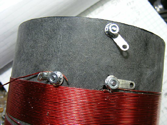
The finished inner coil on the right. NOTE the winding transistion in the middle from one side of the form to the other.
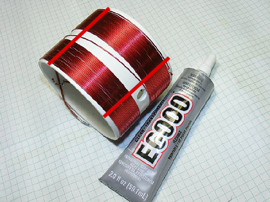
When loose windings keep you awake at night apply a little E6000 in a small vertical strips, DO NOT cover the entire coil it will effect the Q just do a couple of narrow vertical strips across the coil.
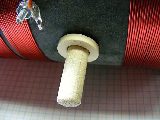
Bushings are available hanging on the wall in the plumbing section with all the small parts at Lowe's This particular bushing was cut in half and for hold the tuning shaft. I had to use a round file to adjust the inner diameter. I don't remember the part number. Play with it. You want a little binding on the tuning shaft in order to hold the inner coil in its "tuned" position.
Coupling or fitting available in plumbing section - trim to size to make a bushing for the 3/8 inch dowell.
"Improvise-Adapt-Overcome"
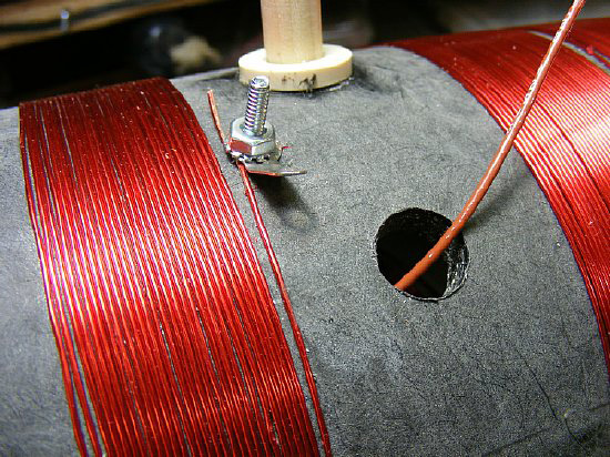
Make the inner coil lead access hole big enough to be useful. Since I was playing with different inner coils I make a large enough hole for easy access. The large hole also gives room for the lead to move back and forth. In this photo the brown lead will be connected to the 4-40 terminal, be sure an leave enough slack so that the inner coil can turn without binding. Play with it.
TIP:
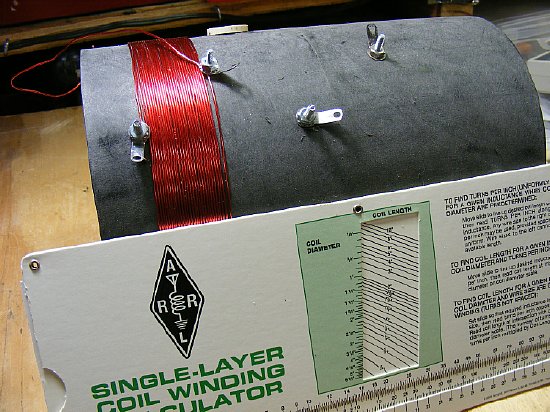
Go to the ARRL site and purchase a "Coil Winding Calculator"
its cheap and helps your make coil predictions and calculations. Great
simple to use tool. Order one as it will come in handy and you can make
real time instant calculations and do real radioing.
Great for "What If" questions
such as changing the wire diameter, number of turns, size of the coil
form etc.
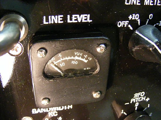
Sensitivity
Testing (Remember that radios have feelings too.)
The R-390 line level meter can be used for
an easy measurement of 10 dB S/N +N as all you need is a signal generator.
I ran several 10 dB sensitivity tests on my receiver in the 300-400 kcs
range and found that the figure was in the 1 to 2 uV range but I must
add that it is hard to efficiently couple the signal generator to the
input coil as it is not 50 ohms and I got lazy and did not want to build
another matching network.
Other rough sensitivity tests indicate that I can easily detect by ear with the BFO on and max RF gain levels in the 1 to 2 uV range and if you listen carefully you can beat the 1 uV range.
Please Note: Using the R-390A on the new amateur band of 472-479 kcs really does not need an input coil and E209 mixer injection so you can use the normal antenna input. But expect rapid decoration of sensitivity below this range.
CLICK
to enlarge
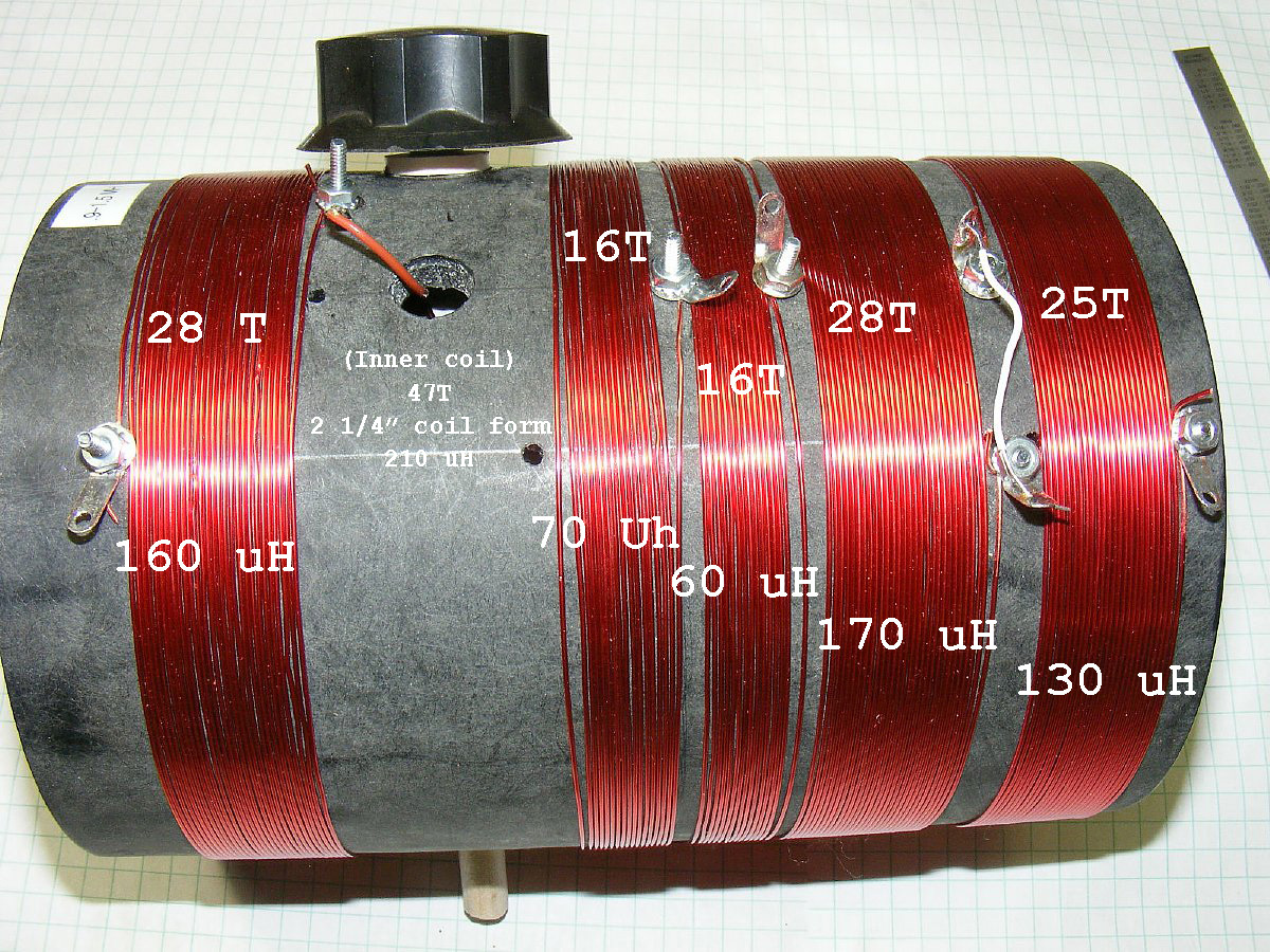
Actual turn and "approximate"
inductance values for each coil segment on one of my coils.
Note:
That the tuning coil to be fully effective it has to be inbetween two
windings and centered.
Total
maximum and minimum inductance on the coil above can be
varied between approximately 100 uH and 1.5 mH depending on taps on the
outside coil and position of the inner coil. The coils interact with each
other so the maximum inductance is hard to calculate and the total will
be more then just adding up the windings. PFM. When positioning your tap
be sure and include the variable winding in your selection to enable the
variable tuning of the coil. You will figure it out. Its real Radioing.
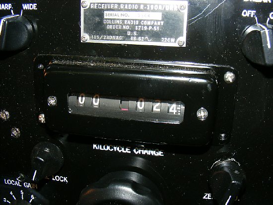
Reception
at very very low frequencies is possible here I am tuned to NAA at Cutler
Maine.
R-390A
Reception of NAA on 24 kcs here in Chickenland.
Details
of NAA can be found at "Navy-Radio"
http://www.navy-radio.com/commsta/cutler.htm
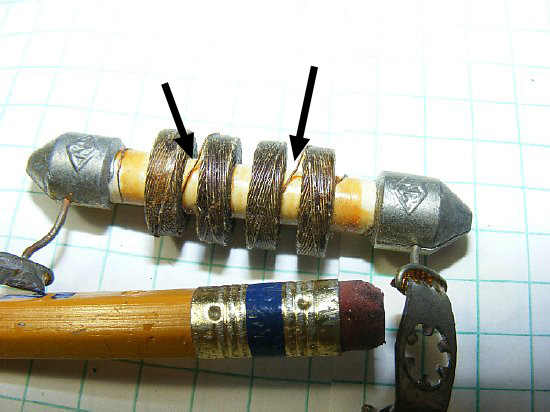
TIP: Need more inductance to put in series with your tunable variometer for use on a lower frequency that is out of range of the home brew coil? Use a 2.5 mH choke - you could even tap it in between the windings (see arrows) . BUT the Q will be lower than the larger size coil you wound.
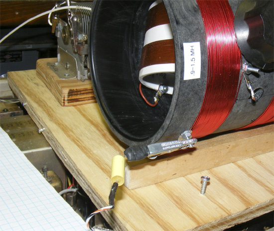
Finished coil with variable capacitor. The capacitor may help in parallel with the coil in certain instances but in most of my test with several random wire antennas it was not needed.
Continue to page 2 for a different tuning coil.