 R-390A "Transceiver"
 1. June 14, 2016 added addtional note on keying the mixer instead of the oscillator. Suggested by W8AU.
![]()
R-390A
Low Power 80 Meter CW Transceiver K4CHE
I
had been restoring my flea market "MRCA Gilbert" purchase and
after replacing the usual capacitors and doing a complete alignment the
overall process renewed my interest in the receiver's excellent stability
and just superb overall performance. After checking and calibrated
the VFO (PTO) I realized that the VFO (PTO)* output
could possibly make an excellent frequency source for a transmitter. Transceiver?
Thus the old K4CHE aphorism applies once again that "Once you start
a project it will spawn yet another project."
* VFO
also know as a PTO.
Note: Years later Collins referred
to their VFO as a Permeability Tuned Oscillator or PTO. The PTO circuit
uses a variable inductance for tuning and is essentially a rod of ferrite
that can be screwed in and out of a fixed tuning coil. Some of the early
automobile radios used the same tuning which saved space and provided
a rugged and reliable tuning circuit in minimum space as well as cheaper
components utilized during production.
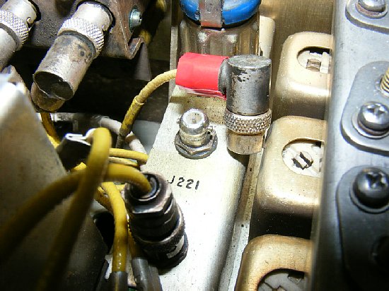
The
P717 output connector from the PTO(VFO) feeds J221 in the Mixer RF section
on top of the chassis. A long shielded cable connects the PTO(VFO) from
underneath the chassis to J221.
Problem: There may not be enough RF voltage from the VFO to supply the receiver and provide additional drive for the first stage of the proposed transmitter. Some sort of "splitter" will have to be constructed.
First: Measure the PP voltage from the VFO.
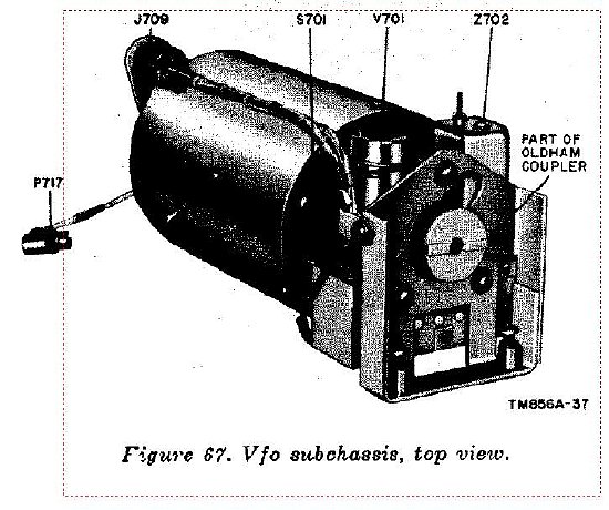
R-390A VFO subchassis and the long P717 cable.
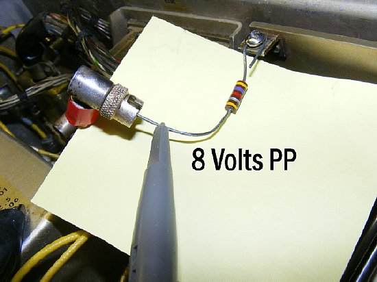
A temporary load was connected to end of the VFO cable. A quick scope check resulted in a measured voltage under the 4700 ohm load of 8 volt PP. Next measure the peak to peak voltage when the resistor load is connected in a "T" fashion and the circuit is completed to provide drive to the R-390A mixer input at J221.
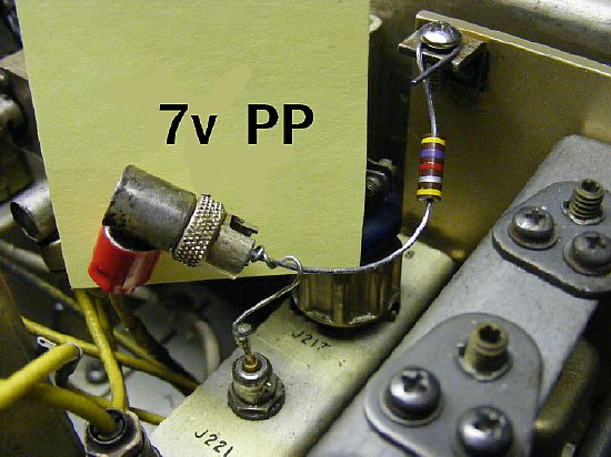
We then measured the peak to peak voltage with a improvised "T" connection. The VFO cable feeding J221 for receiver drive and a 4700 ohm load simulating a feed to a external circuit such as a 6U8 mixer. A whopping 7 volts peak to peak was measured under load and the receiver performance was not degraded. So the decision was made to press on with the mission and provide "Proof of Concept".
This whole project started when I was checking
"End Point Alignment" of the VFO. I found that the R-390A Variable
Frequency Oscillator had an excellent band spread, was very robust mechanically,
and the frequency output was stable even without engaging the internal
heater.
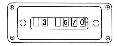
An interesting point about
the receiver VFO/PTO is when you tune the kilocycle knob for a higher
"indicated" dial window frequency the VFO tunes lower
in frequency.
Since
the PTO frequency output is outside the ham band I decided that some sort
of oscillator/mixer would be required to produce an in-band frequency
output for frequency control of a external transmitter and the transmitter
frequency must correspond to the R-390A frequency window indication. In
other words Transceive.
I
looked around at some of the older ham publications and found a converter
article in GE Ham news (more info below) using the very reliable and versatile
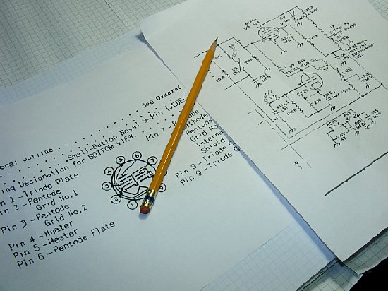
dual section 6U8 tube as a oscillator and mixer. The 6U8 has a 3 element
section and a 5 element section and electrically is two tubes in one glass
envelope. The plan will be to use the 3 element section as a fixed crystal
oscillator and to use the remaining section to do the actual mixing of
the R-390A PTO with the crystal oscillator.
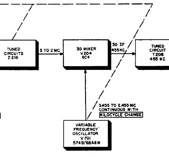
As the large center "kilocycle change" knob is turned clock wise the frequency indicator window increases in frequency as the receiver is tuned higher in frequency but the VFO/PTO assembly output goes lower in frequency. The range is 3.455 kc to 2.455 kc and covers a 1 Mc band segment.
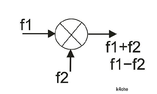
When mixing two different frequencies the output is a combination of the two frequencies. The trick is to choose the correct combination. In this case F1 represents the R-390A PTO output. F2 is a crystal controlled fixed frequency oscillator. Since F2 remains fixed and F1 tunes 3.455 to 2.455 the top combination F1+F2 will actually go lower in frequency as the receiver kilocycle knob is tuned up through the 80 meter band. The lower combination F1-F2 will track higher in frequency as the PTO is tuned and the receiver is tuned higher in the band. Confused yet? Hang on more to come.
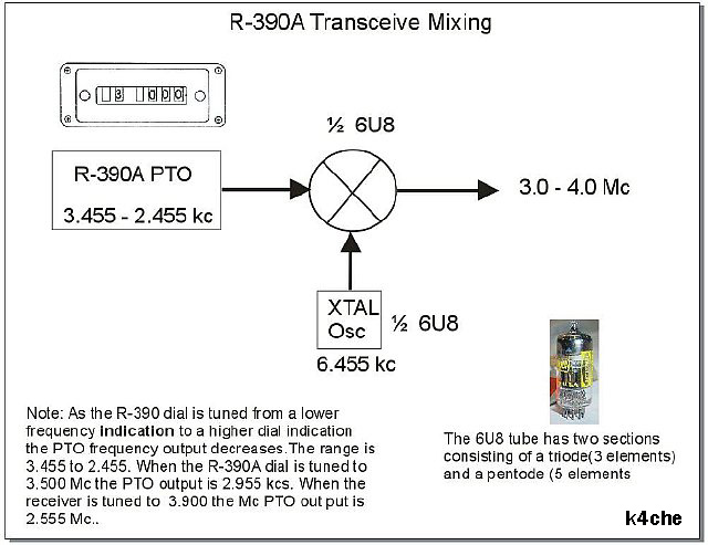
When the receiver Kilocycle
dial is turned to 3.600 Mc the R-390A VFO (PTO) output is 3.455
kc minus 600 kc which equals 2.855 kc. If you mix 2.855 kc with
the crystal controlled oscillator of 6.455 kc using F1-F2 (F1 minus F2)
the resultant is 3.600 Mc which will allow you to drive a companion transmitter
and operate transceive.
As the main Kilocycle dial is turned higher in frequency the VFO(PTO) output decreases in frequency.
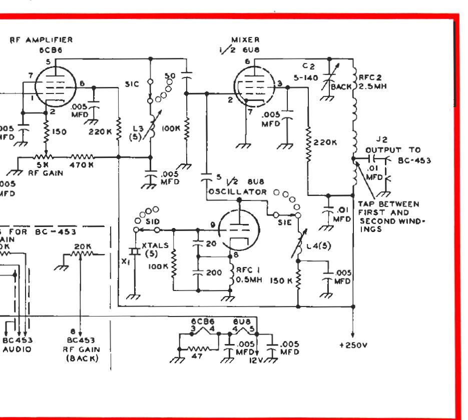
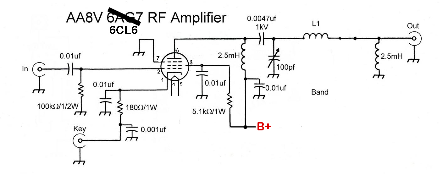
September 1960 GE Ham News
Here is the schematic of the oscillator mixer stage used in a converter published in September 1960 GE Ham News. I modified the circuit slightly and have posted the schematic below. If you look carefully at this schematic the author did a tap on a 4 section RF choke (a standard 2.5 mH choke ) to provide an output but I decided to use a standard tank coil and a simple 2 turn link. I thought that the tapping between the sections of the RF choke was unique but too spooky for me.
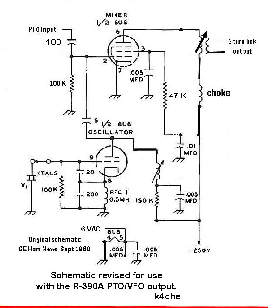
On 80 meters for "proof
of concept" the plan will be to use a 6.455 crystal in the oscillator
section. The final 6U8 plate output will be tuned with a slug tuned coil.
A two turn link coupling is utilized for output.
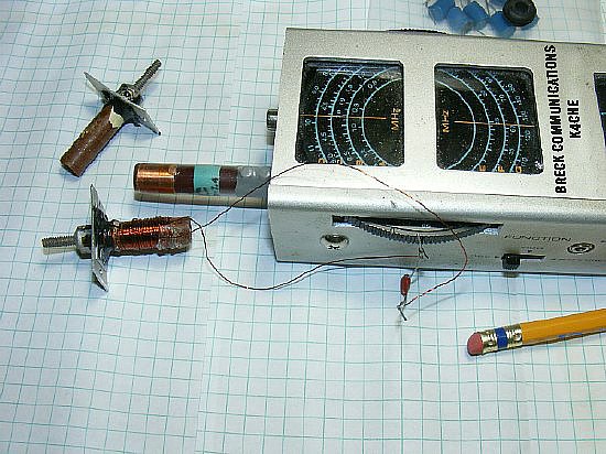
VFO
amplifier works great on a BC-221.
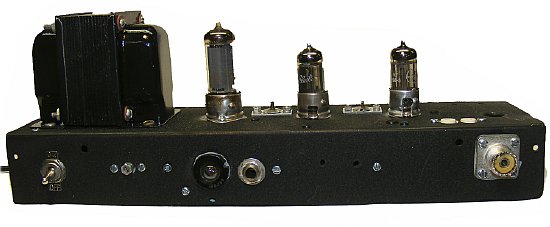
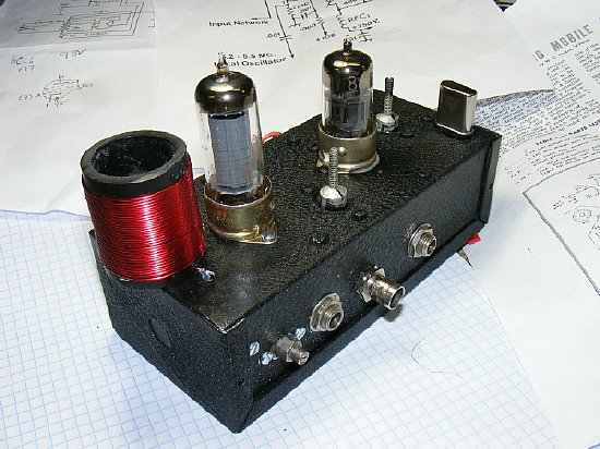
Expecting a very low peak to peak voltage from R-390A VFO but then actually measuring a large 7 to 8 volts peak to peak voltage I was encouraged. So on with the Mission plan. I decided to built a 6U8 oscillator/mixer on a small chassis and then use it to provide drive to my VFO amplifier/transmitter which was an earlier project and is shown above.
But
I also had a simpler plan for a low power QRP stage and that will
be described below.
Details of the 6AH6/6CL6 amplifier/transmitter
shown in the picture above can be found at:
http://k4che.com/BC221/BC221pg2.htm
Details
of a simple oscillator/mixer stage will be shown below.
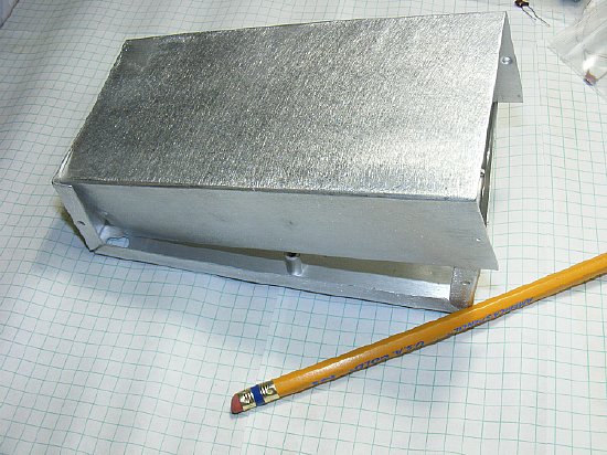
Nothing like starting a project with a nice blank chassis - well all most blank as it is a recycled chassis found while "Hanzing" through some boxes at a ham fest. Some holes are all ready drilled.
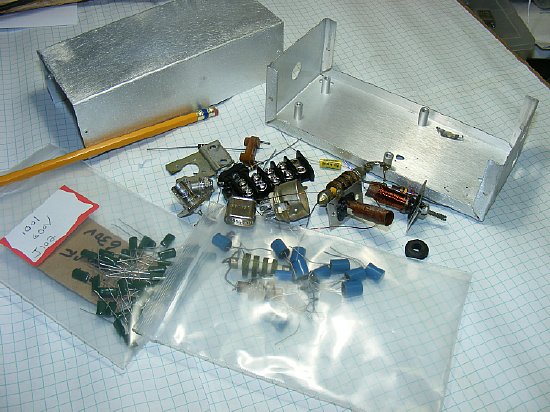
First order of business is to gather up all the parts and order anything that was missing. For most builders it is the coils that present some sort of construction challenge. The oscillator crystal (6.455) for the 80 meter oscillator mixer version can be ordered from BOMAR and more information is presented below. In this case I had a junk box crystal that was on 6451.0 kcs which was close to 6.455 which was what I eventually will need, but close enough in frequency to accomplish testing. Anyway I can build the oscillator/mixer circuit and test it on the R-390A.
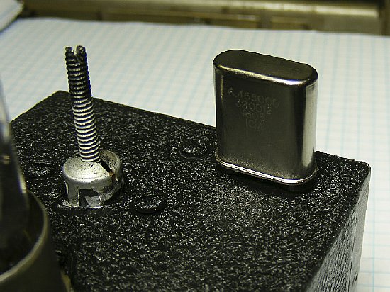
Order
a crystal now as you work on the project. Specs below. If you want to
borrow a "test" crystal e-mail me.
International
Crystal is no longer in business
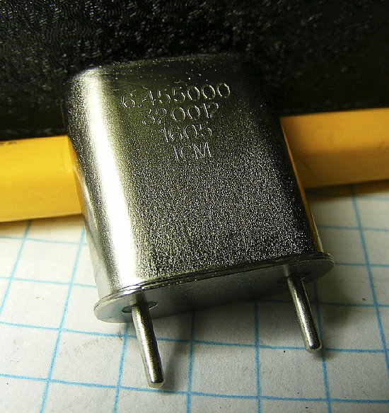
International
stamps their crystal with house markings which depict the specifications
for the crystal. I ordered for this project a "CR18A/U 5-20MHZ
Catalog number 320012. Fundamental frequency
6.45500 kcs. Be sure and request the proper holder in this case it was
a HC-6/HC-48.
The HC-6 and HC-48 holders
have the same physical specifications. By ordering a CR18A you are ordering
to a military electrical specification and with a load factor of 32 pf.
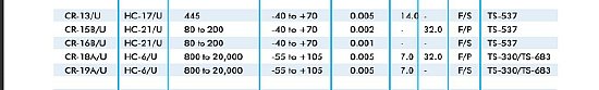
A nice site to check on crystals specifications and download their PDF
file.
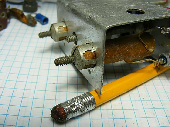
I found some slug tuned coils in the junk box. They will be rewound and remounted. These type of coils are usually mounted through a hole in the chassis with small tabs on top holding them in place.
These "tab" type of coils often when when salvaged from a junk chassis have tabs that break off so I just remount them with a small plate and use JB Weld for glue. Kind of messy but I was in a hurry because I was using the 5 minute epoxy. With this type of chassis mount you do not have to worry about breaking off those pesky tabs and the best feature is that you can easily remove the coil assembly from the chassis for any changes in windings.
Each coil had about 65 turns. #28 wire was used, its not to big , easy to work with, and does not break unless you really pull it tight. Try to distribute the windings evenly but at this frequency it is not critical. Using a 20 pf cap I grid dipped the coil to check approximate frequency range with the slug in and out.

On the lower "HF" frequencies parts layout is not that critical but a rough plan helps when drilling holes and mounting components.
CLICK to enlarge
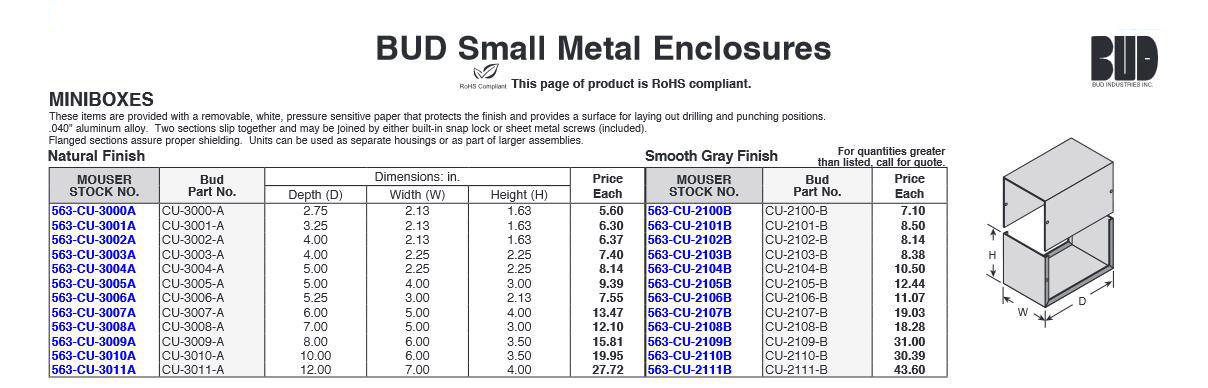
There are plenty of sources for BUD enclosures. ePay, Mouser etc.
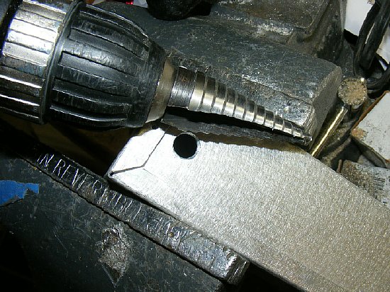
My favorite chassis tool. A Unibit Step Drill. Dangerous. Use a vice as a holder for your chassis box- update your insurance.
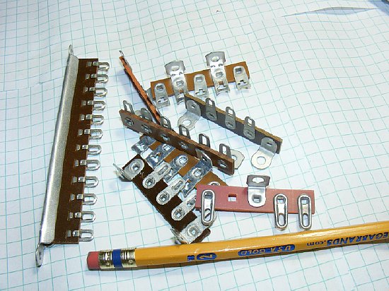
Lug type Terminal strips. Handy during construction.

A favorite tool a Heathkit nut holder.
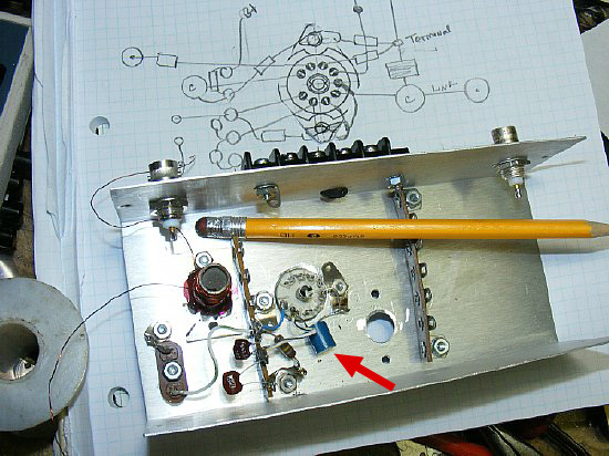
"I love it when a plan comes together." But all ready I am looking at that blank space remaining for maybe adding an amplifier stage? The oscillator stage is shown just about completed but later that puny miniature blue choke for the oscillator cathode will be replaced (it was a terrible choke) and a new larger traditional litz wire choke was added as well as a CW keying jack for the oscillator cathode.
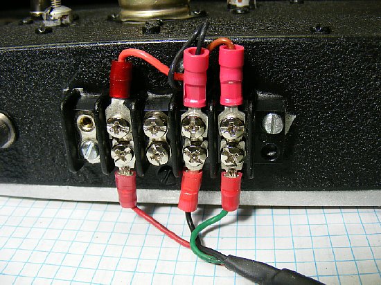
A standard barrier strip was used for power.
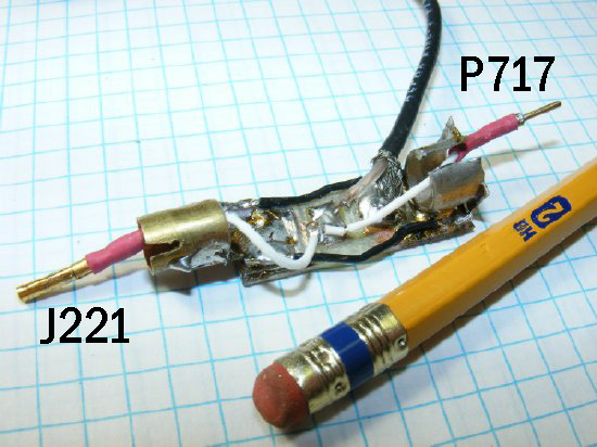
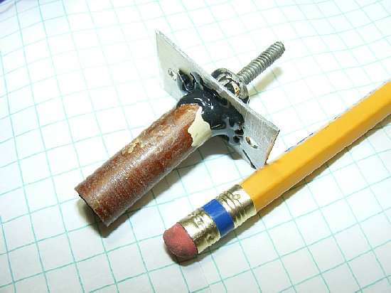
My 15 minute "Emergency T Connector". The female pin for J221 and a male pin for P717 were scrounged from old connectors. I know it looks weird but you will figure it out. A short piece of brass tubing on one end with a slot and a outer housing from an old phono connector on the other end mounted on a small piece of printed circuit board with an connection "island" in the center. The brass tubing end fits over the chassis connector J221.
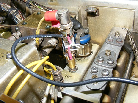
The
"Emergency T" in place. Once nice thing about working with the
lower HF frequencies is that you can get away with a jury-rig T connector
as shown. In this case with a R-390A VFO output frequency range of 3.4
to 2.4 Mc there will be very little loss as long as you have good electrical
contact and keep the unshielded leads on the fabricated T connector short.
Make sure there is a connection between the shields. Standard RG-174 is
used to provide RF to the K4CHE R-390A "transceiver mixer."
"Improvise-Adapt-Overcome"
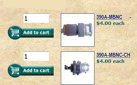
Connectors
used in the R-390 are miniature type of BNC and they are call MB connectors
and can be purchased from Fair Radio. Possibly fabricate a T connector
assembly with the proper connectors?
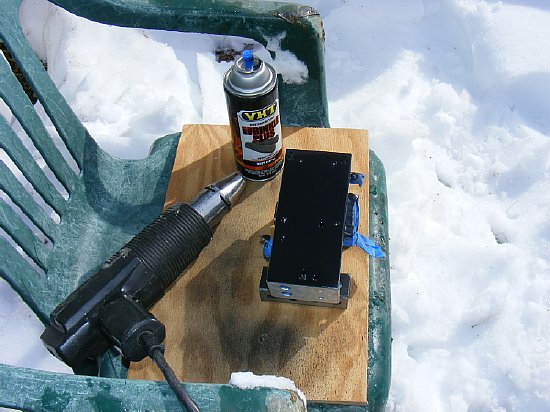
Usually on my projects I prefer to go ahead and paint prior to final completion. I know that if I put off painting to "later" that "later" usually does not get done. It was around 35 degrees F outside - - - I have never attempted to paint with black wrinkle in cold temperatures so I decided to experiment.
Due to the cold temperatures here in Chickenland (snow) I heated the chassis first with a hot air gun. The brand of the black wrinkle paint is VHT - - - absolutely the best wrinkle paint I have ever used. Purchase a can at your local Auto Parts store. Tell em I sent you.
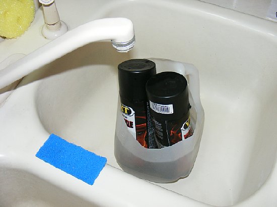
For
best results always preheat "any" canned spray paint with by
immersing in hot water prior to application regardless of the outside
temperature summer or winter.
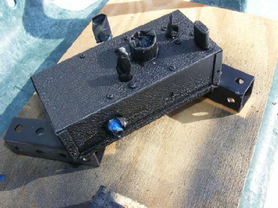
30 minutes later and a nice wrinkle. Due to the cold outside air temperature I did help some areas dry with the hot air gun. Note the painted crystal. I did not forget to remove it prior to painting but I used a spare crystal to plug into the socket to cover it instead of masking it with tape.
CLICK to enlarge
Photo of mixer only version without an amplifier. An additional stage of amplification will be added in the blank chassis area to the left.
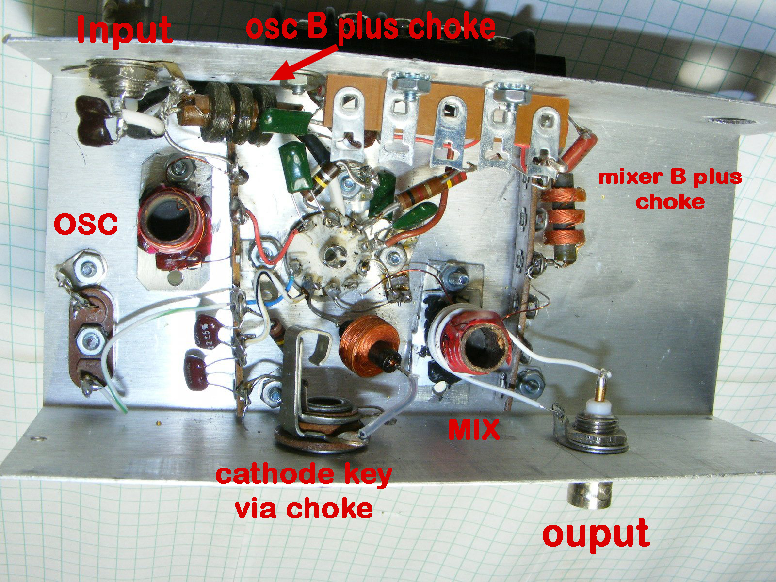
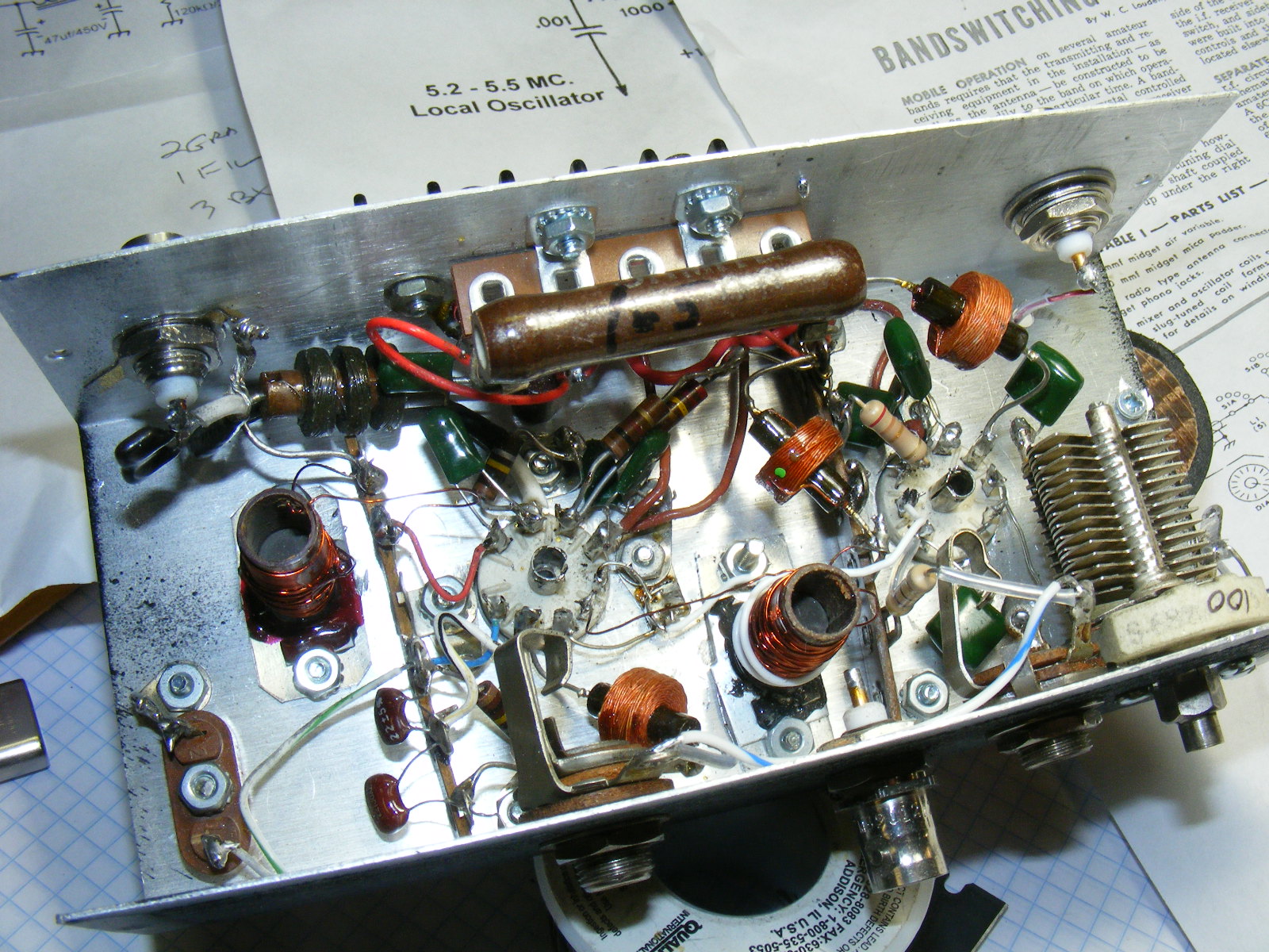
The actual mixer stage has been wired and the project is just about finished. Note the 2 turn link on the mixer coil output. The phone jack will key the oscillator cathode via a RF choke for CW which is not shown on the GE schematic. Red tape holds the turns in place on the coils until the final turn count has been determined after testing. Link coupling (2-3 turns) from the mixer to the BNC is slightly critical adjust position up and down on the mixer coil for best output.
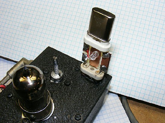
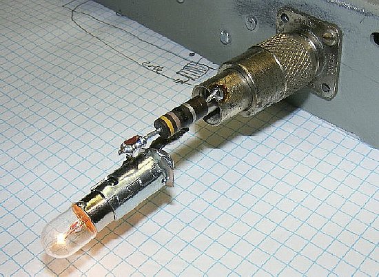
Any oscillator circuit should be checked for current. The test device above uses a 30 ma miniature bulb. Beware of high currents especially when using the new crystals in older equipment. My rule anything over 15-20 ma may damage the crystal especially the new ones with small crystal blank area. In the case above I could not observe any bulb activity which indicates very low current.
CLICK
to enlarge
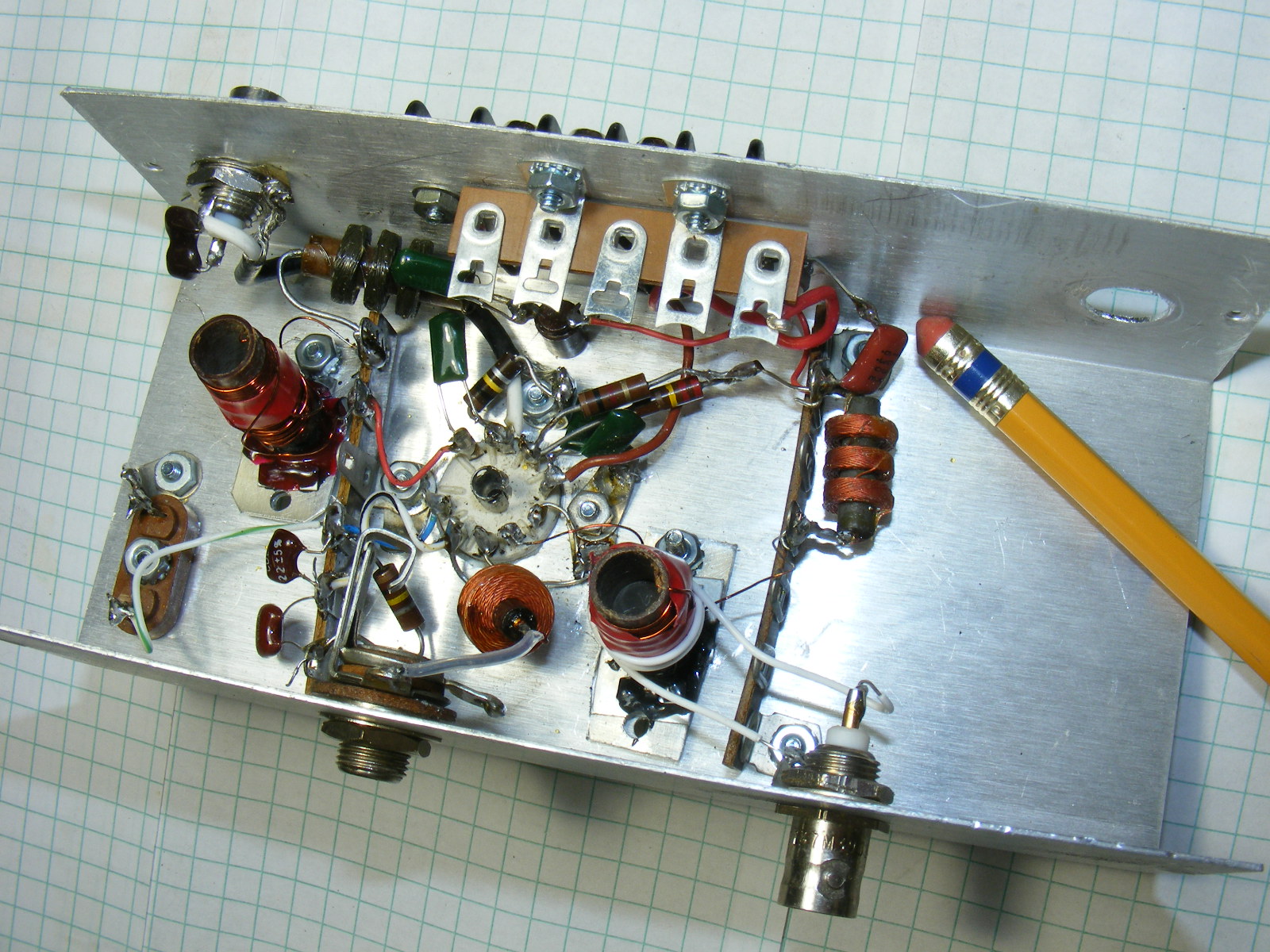
Another
view of the final wired oscillator mixer chassis. The blank area to the
right beckons - - I would have enough drive off of the mixer stage to
drive my previously constructed VFO amplifier. But maybe I could construct
a 6CL6 stage and have enough drive from the mixer section to produce a
watt or so and just use the chassis barefoot on CW (QRP).
Perhaps with the 6CL6 I would have enough drive for the GRC-109 or
RS-6 transmitter.
The
previously constructed VFO amp:
Original schematic by AA8V
A 6CL6 amplifier stage will be added to the remaining blank area on the chassis.
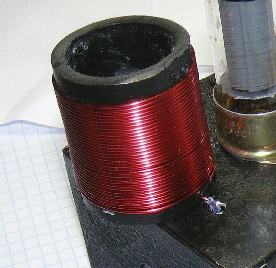
Hams don't like to wind coils. Most won't even begin a project if it involves a coil. Its called "coil phobia".Coil winding is a lost art but definitely not rocket science. The final tank coil L1 shown above for this project is a 15 minute project. Note that the winding is fed through the chassis and is covered with insulation. Simple.

PVC pipe is an excellent coil form for low power levels.
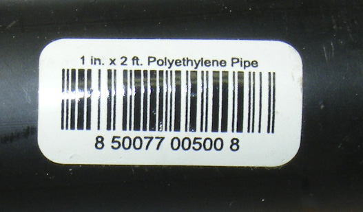
The 1 in. pipe has a inner diameter of 1 inch but the outer diameter is slightly larger that 1.25 inches.
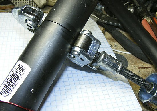
A standard pipe cutter is used to make the initial cutting groove and then usually I use a coping saw to finish using the grove as a guide.

A wooden dowel in the center can be used with a wood screw for mounting to the chassis. Note that the coil wire has been secured through two small holes. Secure the wire first then insert the wood dowel.
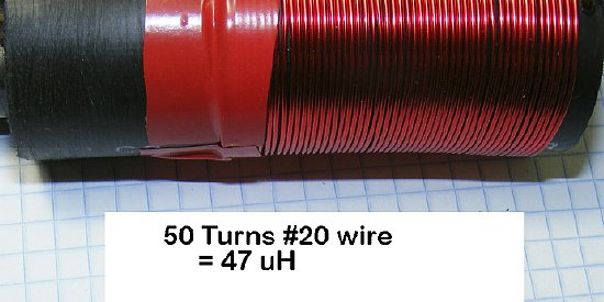
Too much inductance and the actual coil length was kind of long so I used my ARRL turns calculator to determine the winding length for a 30-35 uH coil. The coil was rewound.
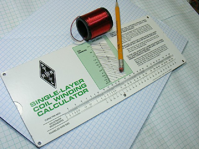
ARRL Coil Calculator. Store item # 9123. If you have one of these on your work bench you will be doing some real radioing.
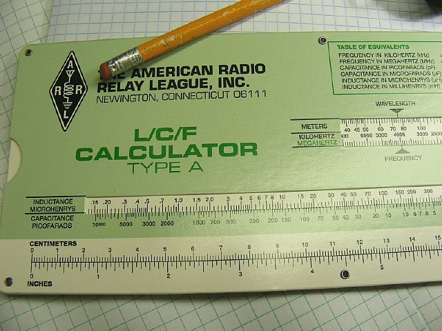
The flip side has a L/C/F calculator and a handy ruler on the bottom.
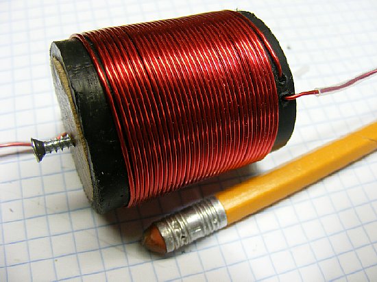
35 turns resulted in a 30 uH coil and it was shorter in length, I wanted at least 30 -35 uH to keep the actual value of the variable capacitor used for resonance to a low value. Note the dowel and wood screw for mounting. Small holes hold the turns in place. Simple easy construction.
A simple L network was used to match the output of the 6CL6 to 50 ohms - this arrangement was selected as the R input (6CL6 output) is higher than the output load resistance (high to low) which is assumed to be a 50 ohm system. Since the plan was to use this circuit on 80 meters and cover a small frequency range the final tank coil L1 does not have any taps. In the event the R Input were smaller than the load resistance then the capacitor would have been placed on the other side of the inductor.
CLICK
to enlarge
In
this photo the link coupling on the mixer coil has been removed from the
BNC connector and attached to the grid pin of the 6CL6. I left the BNC
connector on the chassis for "barefoot" mixer operation so the
link can be either connected to the input of the 6CL6 for high drive or
to the BNC for low drive. The variable capacitor is 10-100 pf but a smaller
value can be used.
A
handy on line resonance calculator can be found at:
http://www.deephaven.co.uk/lc.html
Oscillator/Mixer with 6CL6 amplifier.
When I started this project I had intended to just build a single tube oscillator/ mixer stage. But the project grew when I decided to see if I had enough drive for a 6CL6 final. The final tank coil for the additional 6CL6 amplifier sticks out over the edge in order to provide separation. This arrangement tuned well and there were no problems. The screw driver adjustment on the left front of the chassis is the final variable capacitor. The output BNC from the 6CL6 is on the rear. When using just the mixer output for low drive then the front BNC can be used. There are two phone jacks for keying as I at first keyed the oscillator cathode then I decided to key both the final amplifier cathode and the oscillator cathode so I installed a phone jack closer to the 6CL6.
A note on keying. W8AU emailed me and asked the question. "Why did you key the 6U8 xtal osc instead of the normal method of keying the mixer, which allows a lot of waveshaping without affecting the frequency? "
My Answer: I keyed the xtal osc because that was what I have always done in the past just a construction habit I guess. Usually my simple transmitter projects do not include a mixer so it did not occur to me at the time to key the mixer cathode. Keying the osc did not produce any large frequency varations or chirp but I will try keying the mixer in the next version as it obviously is a better design. Thank you Perry.
A
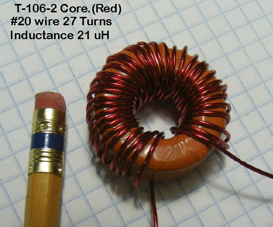
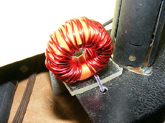
10 minute coil project. I usually wrap the core in this case a T-106-2
with plastic tape prior to winding for additional insulation and it keeps
the turns from sliding. DO NOT cover the entire core with the wire windings.
Leave a space as shown.
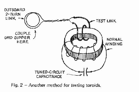
QST January 1974 p16.
Remember that the toroid coil is "self shielding" you will have to use a "test link" to couple the grid dip meter if you decide to check for resonance. Use a small capacitor such as 10 pf across the normal winding.
Mount on a small piece of lexan, insulate the leads, and then feed through the chassis. Simple.
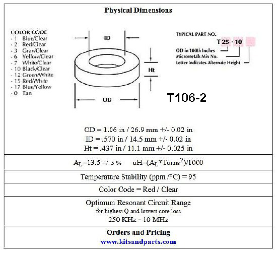
Info
on the T-106-2 Red Core.
Here
is a great Toroid site. Be sure and check out the "calculator"
tab and other help information tabs at the top of the page.
http://www.kitsandparts.com/toroids.php

Handy for testing. On the right is a micro switch "CW key". On the left a switch for constant ON.
You can test the 6CL6 final amplifier output with a #47 bulb (6 volt) - but you may come close to burning it out. Putting a 47 ohm resistor in series helps prevent burn out when used to check output on different projects. #47 bulb is rated at 6.3 volts and .15 amps. Power = 6.3 X .15= .9 watts.
Final Output Testing:
330
volt supply. RF Input from R-390A VFO was measured at 5-6 volts PP at
the input BNC connector prior to the coupling capacitor. RF output from
the 6CL6 was .7 watts . Easily lights a type 47 bulb (may burn it out).
Measured output voltage was 20 volts Peak to Peak which is enough drive
for the average transmitter injection at the crystal socket.
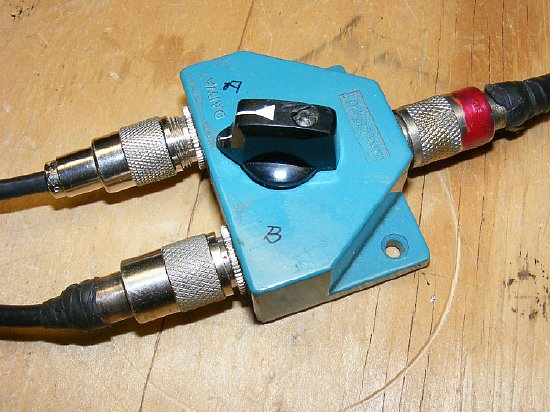
Antenna change over for the "Proof of Concept" was accomplished using a switch.
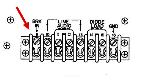
The R-390A has a Break In function. Grounding this terminal with a relay or small switch when going to transmit will disable the receiver but for now I just turn the RF gain down when transmitting.
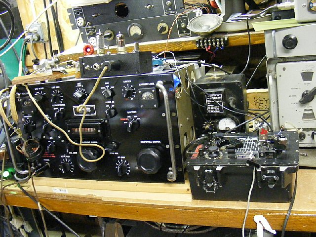
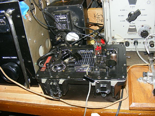
R-390A Transceiver K4CHE
R-390A Transceiver ready for action on the MRCA Sunday Night CW net held at 21:00 hours, Ted W3PWW is the NCS. Frequency 3.570 Kcs. The two tube mixer/oscillator portion of the R-390A transceiver sits on top with the antenna change over switch to the rear. This funny looking device to the left of the "transmitter" is a telegraph key. Tuning the system to exact transceive is easy.
Video Tuning the System to exact transceive.
There is plenty of drive from the mixer/oscillator. Feed the T-784 transmitter with a short shield cable (as short as possible) to the hot side of the crystal socket and ground the shield.
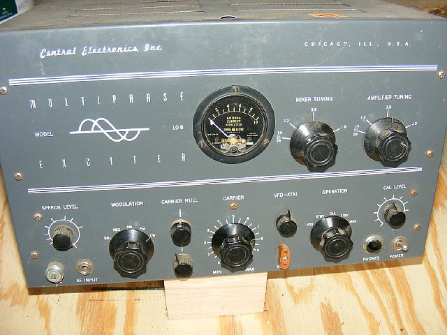
NEXT Project: SSB transceive with the R-390A - Change the K4CHE mixer scheme to produce an output of 5.500 and 5.000 for the mixer of this 10A. I've always like the 10A and 20A transmitters as they have a lot of knobs and require a lot of adjustments - makes you feel like you are doing some real radioing.