Automatic Keyer for CW Using Relays
Revised 12-29
CLICK
to enlarge
In the days before Single Side
Band AM (single side band is AM) hams keyed transmitters by hand
using Morse code which consisted of dots and dashes. Several atomic keyer
circuits were published in CQ and QST to assist this endeavor. The circuit
above which generates automatic dots and dashes was designed by W3FQB
and it was unique as it utilized selenium rectifiers to isolate the dot
and dash circuits thus eliminating a relay. Some of the earlier circuits
used 3 relays.
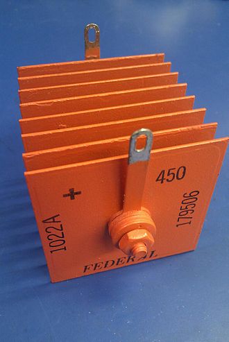
Selenium rectifiers were a big deal in the 1950's. Replaced later by smaller diodes.
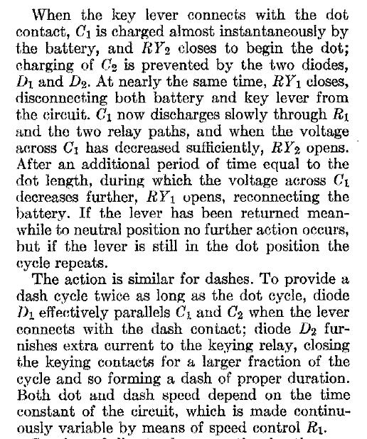
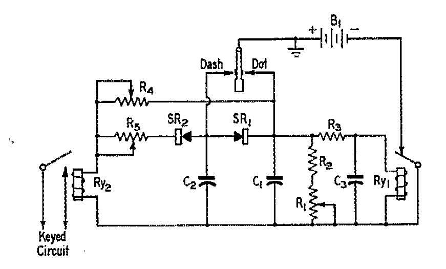
Theory of operation taken from the original article.
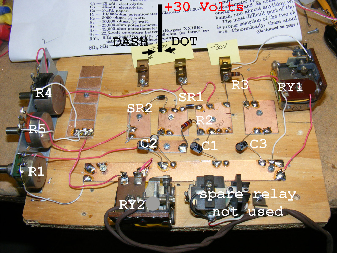
The pots R4 and R5 control dot and dash length. R1 controls the speed. Use 9 volt batteries in series for power. The two diodes (SR 2 and SR1) replaced the selenium rectifiers and are mounted in the center. I used a 22uF capicator for C1 and C3 and then 22uF and 10uF in parallel for C2 this gave me a nice mid range speed of around 8 WPM.
I used several different
types of relays - - - the relay at the upper right RY1 must have a set
of normally closed contacts which open when coil voltage is applied. The
keyer "paddle" provides a plus voltage into the two clips at
the top to provide voltage for dots and dashes.
The keying relay
at the bottom left only needs one set of contacts that close when voltage
is applied to the coil. The other relay at the bottom right is an emergency
spare.
Note
the use of PC board squares for soldering components. A modern bread board.
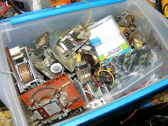
Half the fun is going through your box of relays.
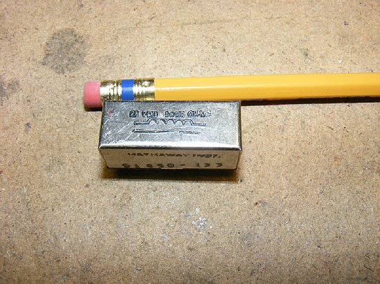
Several reed relays were tested. This one measured at 5000 ohms. Perfect. The only catch is there is only one set of contacts which are normally open so this particular relay can only be used for the final keying relay RY2. RY1 needs a set of contacts that are normally closed. There were reed relays made with double throw contacts so look for them.
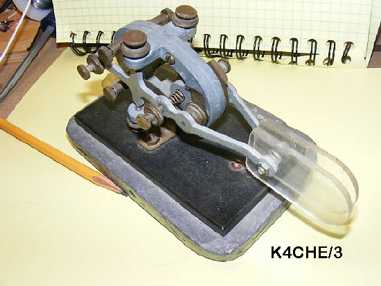
Most of
the early electronic keyer "Paddle Keys " were made from back
to back surplus military keys. The clear plastic paddles replaced the
knobs and were made from Plexiglas found in a trash barrel at a USAF scheduling
office in 1963. The military throws away a lot of stuff. Plexiglass was
a big deal then. J-38's were often used for keyers and were a buck a piece
down on Market Street in San Francisco. A sardine can was used as a mold
for the lead base but remove the sardines first. Later my lead key bases
were painted black to prevent lead ingestion and to provide stealth.
Improvise
- Adapt- Overcome
Photo
by N9SE
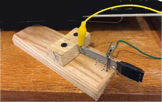
Here
is a simple key using a hacksaw blade as a base. Also known as a Cootie"
key. This one made by N9SE. Note the blade "throw" adjustment
made by using the placement of the nails in the holes.