| FSE 38 Power and Tune Up Instructions 3/14 |
An attempt has been made to write this procedure for
those without a shop full of test equipment.You don't need to build a
test set.Many thanks to Brian Clarke VK2GCE who helped me test this procedures
and helped with the technical details.
Equipment needed: VOM, scanner or receiver, test transmitter.
General: The transceiver contains a receiver and transmitter module. The transmitter module is marked "Sender" and is located on the top of the unit. The unit shares a single crystal for transmitting and receiving and the I.F. (Intermediate Frequency) is 10.7 Mc's which runs continuously in transmit and receive. The radio is a nice well constructed unit both electrically and mechanically. The unit can be aligned in the range of 38 to 47 Mc* * * or 47 to 58 Mc. It's perfect for short range commo such as conveys,going to get pizza and hamfests.
* * *Hertizes, Megahertizes, Kiloherzskies are not recognized on this site. Wat are we gonna do next call a Motorcycle a Motorhertz ?
Crystals: The helmet receiver a PRR-9 has the same frequency scheme as the FSE 38/58 and the crystal works well in the 38/58. The formula for the crystal is Operating Frequency minus 10.7 Mcs. Calculating an Operational frequency of 51.0 Mcs the crystal frequency is 51.0 minus 10.7 which equals 40.3 Mcs.
51.0
minus 10.7 = 40.3
So if you are ordering a crystal for 51.0 Mcs
you order one for 40.3 Mcs in a HC-25 holder with a "series" load capacitance.
Jan Crystals (1-800-526-9825) accepts orders for military type crystals
as per the mil spec Mil-C-3098. The helmet receiver used a "CR-81/U crystal.
Some military radio folks have bad mouthed JAN crystals,
I personally have never had a problem with them, like everything- give
em garbage info and you shall receive garbage products.If I am in doubt
I sent them a sample crystal. When ordering from JAN ask for a CR81/U
military crystal (without the dash as that is the way it is in their system.)
The CR81 is a .005 tolerance rock and can be ordered from 17 to 61 Mcs
and again uses an HC-25 holder. 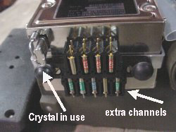
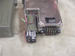
The radio contains a battery case for a 6 volt battery and you can put in 4 double A cells in series to power the radio several users have used a Radio Shack battery holder, the part number is 270-383. The schematic for the radio calls for 5.5 to 6.5 volts for the battery and for external power it lists 20 to 32 volts.

Click to enlarge
Warning: If you accident hook up your 6 volt battery pack backwards and it is not protected by a reverse polarity or series diode (which you must install)you may damage your transceiver.
 The
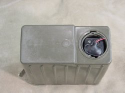
twist cap will no longer fit on the case so put it aside in a safe place
or just chuck it. When you store the radio, you might want to remove the
batteries or unplug and cover the battery case terminals for safety.
The
twist cap will no longer fit on the case so put it aside in a safe place
or just chuck it. When you store the radio, you might want to remove the
batteries or unplug and cover the battery case terminals for safety.
For my bench testing I simple tacked on a red plus wire to the battery case at the bottom and a black minus wire to the chassis of the radio. The 6 volt and 24 volt lines are protected by small 2 amp fuses located next to the battery case.They are vertically mounted fuses and are marked 125v.
Overview: We will align the unit oscillator first using a single point on the "test" connector on the radio, . You will also observe the current draw while aligning the remaining stages of the transmitter. Now is you are lazy and don't want to hook up a current meter and observe the current draw then be prepared for trouble.
Alignment of the "front end stages" of the receiver will be done by listening to a signal generator or a nearby transmitter and only involves tuning two coils as the rest of the receiver does not need alignment
Procedure: The radio has 7 alignment tuning cores that are easily accessible.
Five of the tuning adjustments are on the "sender" and two are on the
"Empfanger". They are labeled 1 through 7 and I will refer to them as
L1, L2 etc. The radio has two rotary switches that are located near the
tuning cores. These switches are turned by a flat blade screwdriver and
have two positions marked A and B. Position A is for 38 to 47 Mcs and
Position B is for 47 to 58 Mcs.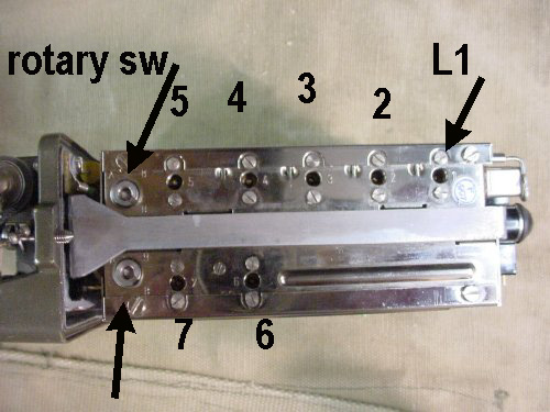
Click to enlarge
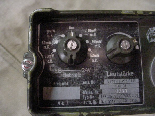
These switches are used to switch small values of "ganged" capacitance in and out of the receiver and transmitter circuits to provide proper tuning in the selected range. The tuning shaft or stub positions in relation to frequency of operation are generally at the bottom or all the way in the core of the coil for the bottom end of each range A and B range. As you go higher in frequency the core tuning stubs will extend out of the core and become more visible. We will "preposition the tuning stubs later in step 3(three). Power up the radio using 6 volts and attach a milliamp meter in series with the plus lead of your power supply. The function switch on the front of the radio selects between the 6 volt positions on the left and the 24 volt position on the right. "Aus" is off. M.r. positions are for squelched operation, o.R is for open, unsquelched operation. Make sure your volume is clock wise.Unsquelched or squelched in the receive mode the radio draws 20 milliamps If it doesn't then something is wrong.
* * * See Glossary elsewhere
1. Determine that the receiver is working by un-squelching, you should be able to hear noise.You do not need a crystal to do this, just simple unsquelch and monitor the current draw of 20 mills. Make sure that your power supply is supplying 6 volts!
2. Fashion a tuning tool out of a 3 inch 1/8 inch brass or aluminum
tubing.Be very careful with this process, it should take about 5 seconds,Take
a pair of pliers and squeeze the tip together to form a flat slot for
the tuning stubs. If you don't have any tubing look in some of the older
ball point pins as they have brass tubing.If you don't have any of the
older ball point pins then your are SOL(* * *). It's fun looking for the
ball point pins, try under your back seat of your car or in the bottom
of your sofa,or chair.
* * * SOL see Glossary else where on this site.
3. Alignment on 51.0 Mcs requires that you preposition the coils by tuning them down (clock wise)into the radio. When pre-positoning the coils don't get carried away and get the coils too far into the radio, they will be hard to get started out CCW(counter clock wise) again. The threads of the tuning stubs should be well down into the radio with just the flat portion of the stubs sticking out a turn or so.
4. Turn both rotary switches to the "B" position for alignment on 51.0 Mcs. Note: You do not have to transmit to tune oscillator coil L1 in the following step number 5 as it is the master oscillator and is used for both transmit and receive, you can tune it while in the receive mode.
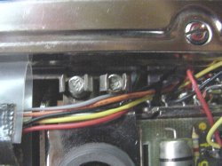
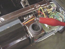
5. Locate the small test connector which is next to the bottom of the battery case and has many little mystery holes in it. Looking at the connector there is a "notch" on the side, the oscillator test pin is located immediately to the left (port side) of the notch. Hook up a voltmeter (preferably analog), select a low voltage scale of 1 or 2.5 volts and monitor from that pin to ground.It is best to use an analog meter instead of a digital for peaking. If you can't get your test probe in the test socket points then try using one of my favorite tools a safety pin

Click to enlarge
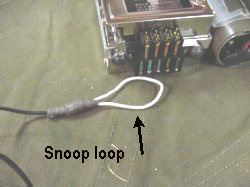
During our alignment we peaked Coil L1 and monitored the test pin voltage and listened on a receiver to the crystal fundamental of 40.3 Mcs(that 40.300 on ur scanner). If you have trouble hearing the crystal oscillator with your "monitor"then fashion a "snoop loop" out of a short length of coax. Put on a connector for the "monitor receiver" and at the end of the 2 or 3 foot coax section and put a two inch piece of insulated wire from the center conductor of the coax to the shield and fashion a small loop. Use this to couple the " monitor receiver" to the area of the FSE 38 coil L1 and crystal. Snoop around for the best signal near L1 and the crystal. As the stage is tuned the crystal will take off and start oscillating then you should have plenty of signal. While tuning coil L1 look at the test meter and peak to maximum voltage around .4 or approximate half a volt. Just tune for peak don't worry abut the exact voltage. Coil L1 does effect the transmit and receive frequency slightly but peaking is close enough for government work.
WARNING: Don't proceed further unless you can get the first stage working
by tuning L1. You will wind up in never never land upon which there may
not be a return portal..
WARNING:Don't tune up the transmitter without a load, you can damage
the final transistor stage.
7. Hook up a handset and be prepared to key the transmitter in the 50
mw range. Position the front selector to 50 Mw. Monitor your current and
again make sure that your test power supply is providing 6 volts. Key
the transmitter and listen on your "monitor"scanner or receiver at your
target frequency of 51.0 Mcs which is the target transmitter frequency.
Tune coil L2 out of the radio and tune for maximum current on the 6 volt
line, you should get a broad peak of at least 5 mills and the current
should get up into 40 or 50 mills.
8. Tune L3 and L4 in the same manner as L2.
9. Tune L5, the tuning is is very broad but again
use maximum current for a broad peak on the current meter.
Note :Eventually our goal is to draw about 100 mills when transmitting in the 50 mw position of the radio. You can monitor your progress and the output of your transmitter by watching for the goal of a 100 mills.
Note: You can not tune L6 and L7 by transmitting, at least I could not
do it. It is a band pass circuit that is shared by both the receiver and
the transmitter. So we tuned 6 and 7 by tuning the receiver for maximum
signal.You can still leave the dummy load on the receiver for tuning the
receiver.
10. Set up your test signal generator or transmitter
on the target frequency of 51.0 and tune L6 and L7 for maximum received
signal which will be evident by the by the receiver noise"white noise"
or static reducing in your handset. Some attenuation of the "generated
signal" will be required in order to peak the receiver properly . If you
are using a PRC-25 PRC-10 etc. you can attenuate the signal several ways.
a. Put the PRC-25, PRC-10 on a dummy load while transmitting. B. Try disconnecting
the dummy load from the receiver as it is acting as an antenna. C. You
can also tune the generator or test transmitter slightly off frequency
as this will attenuate the signal . You can further reduce saturation
of the receiver by taking the antenna off of the receiver.. Tune L6 and
L7 for maximum received signal.
11. You can now go back and touch up the transmitter,
take your 47 ohm dummy load and put a small diode on the hot side(coax
center conductor connection) of the resistor. Connect the anode side of
the diode to the center conductor and the banded side(cathode) to the
plus lead of your meter which still should be set on 1 volt or 2.5 volts
DC, again an analog meter is best. Connect the minus lead of your meter
to the radio chassis. The idea is for your DC voltmeter to sample the
DC voltage produced by the diode as it samples the RF which is AC. Transmit
into this dummy load resistor/diode combination which now services as
an RF probe. LEAVE COIL L1 ALONE!. Peak coils
L-2,3,4,5 for maximum voltage. You should see about .1(point one) volts
on your volt meter scale which is not a lot but it should be observed
and you should be able to peak the stages. Listen on your receiver and
monitor your transmit audio, it should not be distorted, if the signal
distorts or "growls" at you then retune the stage you are working on for
best signal quality. 50 Mw is plenty of power for local contacts and I
don't recommend getting greedy and changing the transmitter power scheme.
When I aligned on 51.0 Mcs, my actual power output around 100 Mw measured
by a HP power meter. You could easily see a deflection on a 5 watt slug
on a Bird Watt meter.