 |
K4CHE GO-9 HF/MF
Transmitter Project: RECTIFIER POWER SUPPLY- Rebuild/Modify to Operational Status |
 |
A Basic Plan A Saga of sorts.
The basic plan was to utilize
the original GO-9 Rectifier chassis and front control panel to house and
control the various power supplies needed to power the GO-9 transmitters.
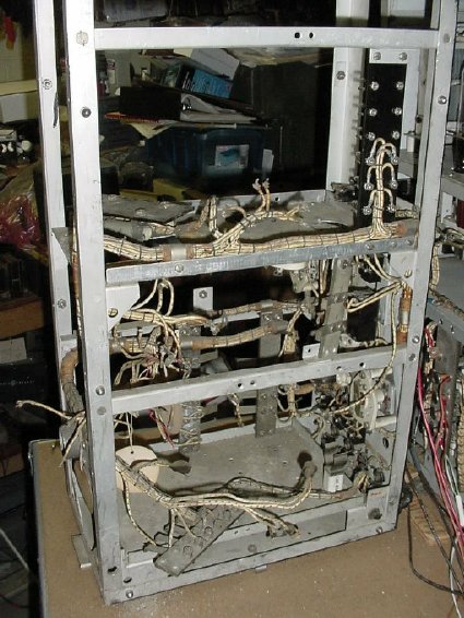
The interior of the Rectifier chassis had pretty much been gutted by
one of the previous owners.
The basic plan was to construct
individual power supply modules to replace the missing power components
and mount them on the gutted chassis. The primary goal was to get the
transmitter operational. This GO-9 equipment is useless to me just sitting
around, I prefer that my equipment be operational and be usable on at
least 80 or 40 meters. Besides it would be fun to check into the Ole
Military Radio CW Net using the GO-9. Sunday evenings at 21:00 hours,
W3PWW NCS on 3.570 Kcs.
a. Each power supply module
would be built on a flat aluminum tray.
b. The trays would mount on the existing Rectifier shelves and be easily removable for maintenance.
c.The
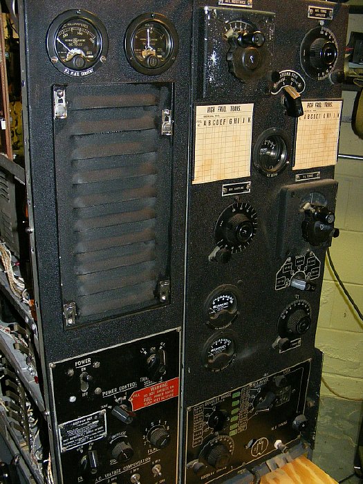
front panel layout would not be altered. The original Metering functions
would be retained.
d. Some switches would
be used for alternate functions but all switches would be operational.
e. Both transmitters would
be operational and the original antenna switching would remain intact.
f. A hidden variac would
control the High Voltage. The High Voltage supply would be remoted.
g. Keying circuits would
remain original, the audio keying monitor would be operational.
Most
of the front panel controls and switches were intact.
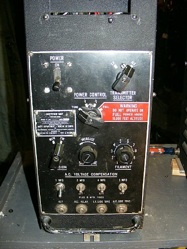
The front panel
was in good shape cosmetically . I was missing the data plate but Mike
KC4TOS came to the rescue.
As I progressed through
this project I decided that complete documentation would be in order due
to the complexity of the project.
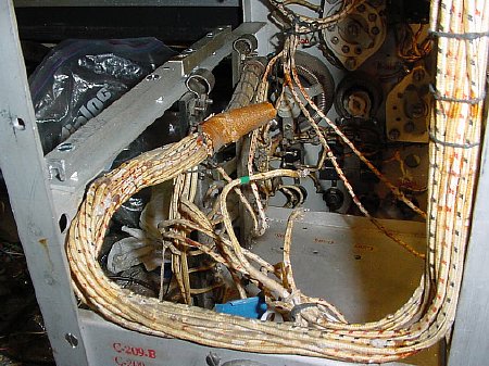
Most
of the wiring bundles had been cut by one of the previous owners so the
decision was made to utilize barrier strips on my power supply trays for
connections and utilize as much of the original wiring as possible. Its
fun tracing out wiring bundles when the majority of the wires are the
same color.
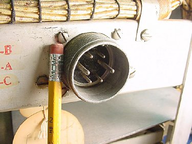
The original main power connector
would be utilized for 120 VAC input. The original wiring used two of the
pins for 120 volts 600/800 cycle AC and pins for a 12/24 VDC input to
power large keying and antenna relays. An internal 12 VDC power supply
would be constructed t to provide this low voltage. A quick call to William
Perry Co. Inc resulted in a mating connector. His phone number is 502-893-8724
and he monitors his fax at 502-893-9220. A photo sent via fax gets good
results. Lt. Col Perry is highly recommended.
 Click
to enlarge
Click
to enlarge
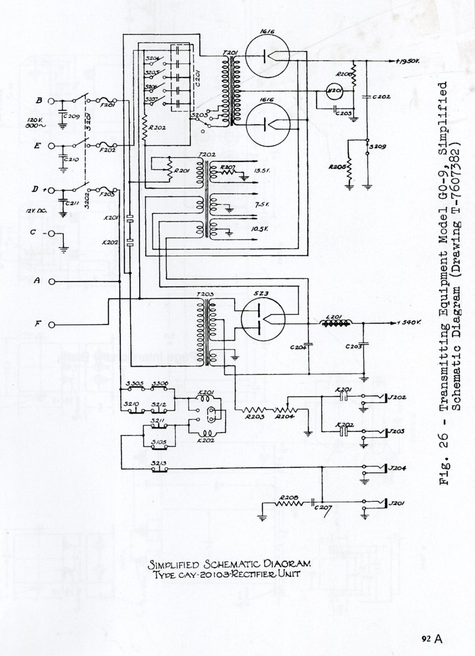
The original Rectifier
utilized 120V 600/800 cycles for primary transformer power and 12V DC
for the relays. The low voltage AC outputs were:
a. 15.5
volts AC via a separate winding on T202 for the 837 oscillator (.9 amps)
and 837 intermediate amplifier filament (.9 amps)
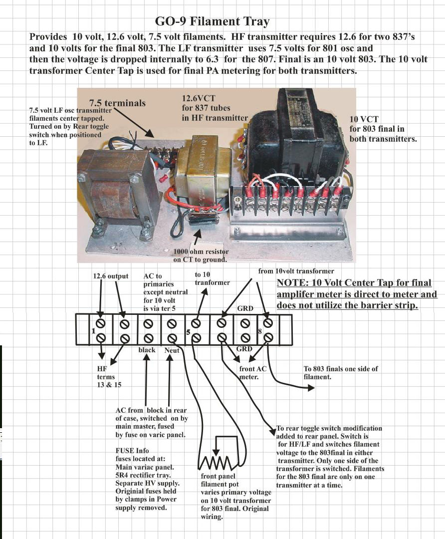
b. 7.5
volts AC on T202 which provided filament power to the 801 oscillator (1.25
amps) and 807 amplifier (.9 amps) in the low frequency transmitter.
c. 10.5
volts AC for the 803 final in each transmitter. The 803 filament
needs 5 amps of current. I planned on switching this voltage between transmitters
so only one tube would be on at a time thus reducing the total current
needed and I would be able to use the 8 amp transformer I had in my inventory.
The high voltage outputs of the Rectifier were:
a.
540 VDC for screen and plate voltages. Total current requirement including
the 803 final PA screen was 210 Ma.
b. 1950
VDC for the final 803 plate. Full power requires 175 Ma.
Note a separate High Voltage Supply was constructed to provide plate voltage for the 803 finals.
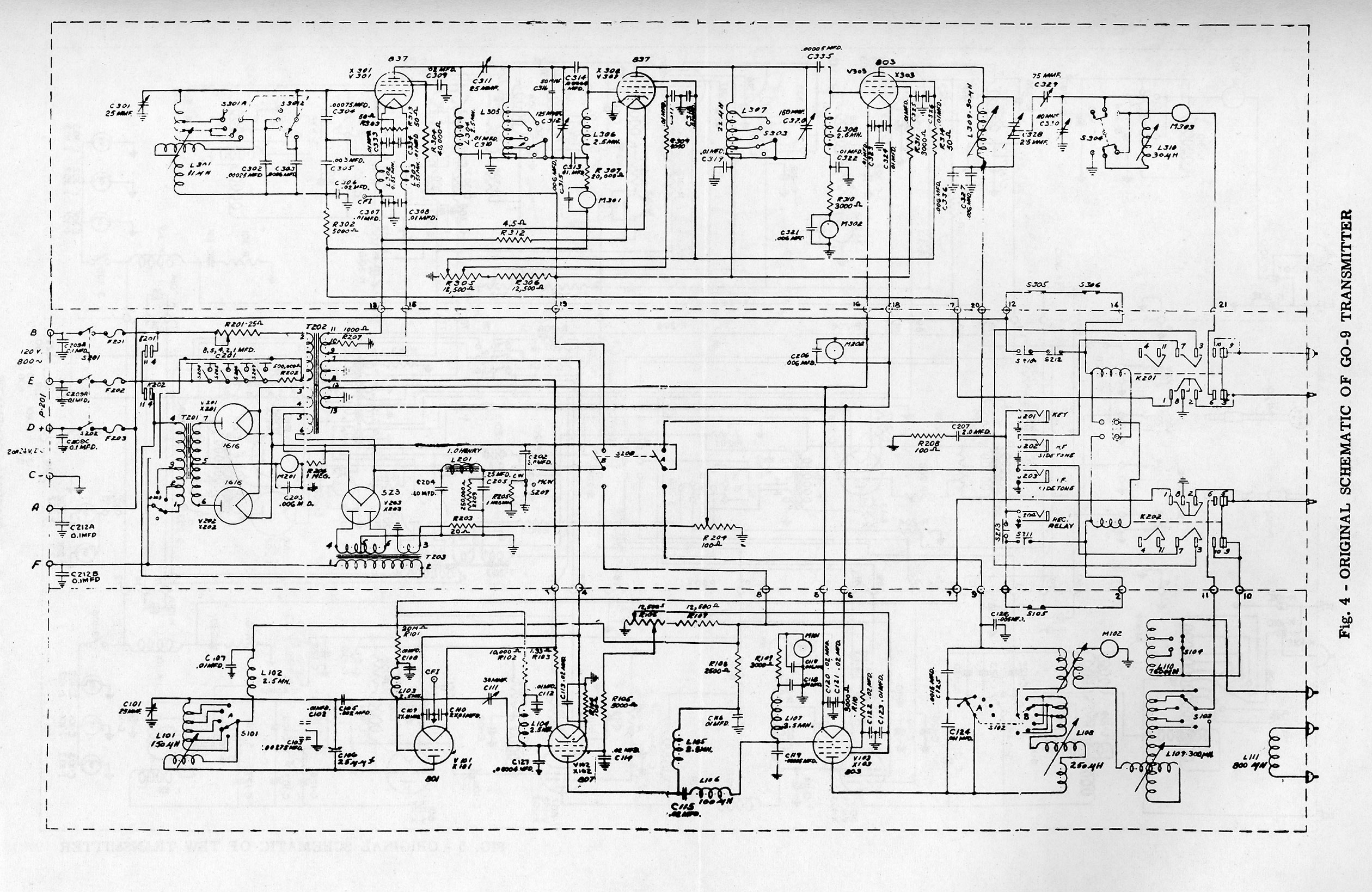
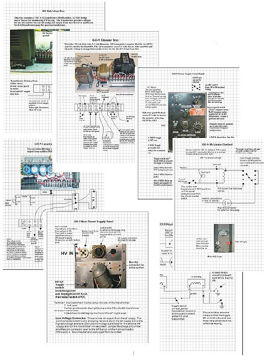
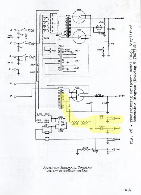
The
entire system schematic.
CLICK to enlarge
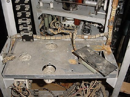
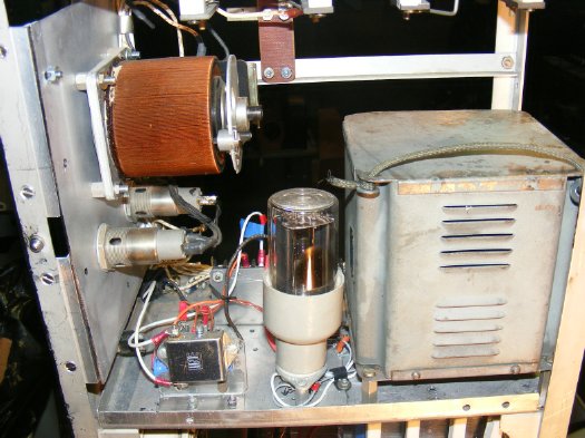
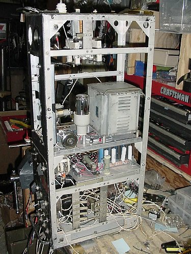
There
was sufficient room on the chassis shelves for my "tray modules".
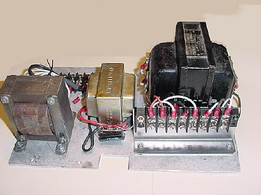
A
typical tray, the low voltage filament transformer tray.
 Click to enlarge
The
barrier strips were originally fastened directly to the trays but it soon
became evident that this was going to be a pain in the xss to install
and remove terminal wiring. so . . .
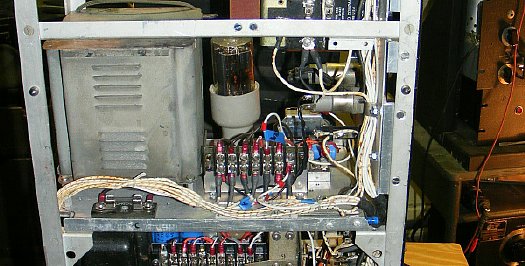
The barrier strips were mounted vertical utilizing small brackets for easier access to wiring and for trouble shooting.
 Click to enlarge.
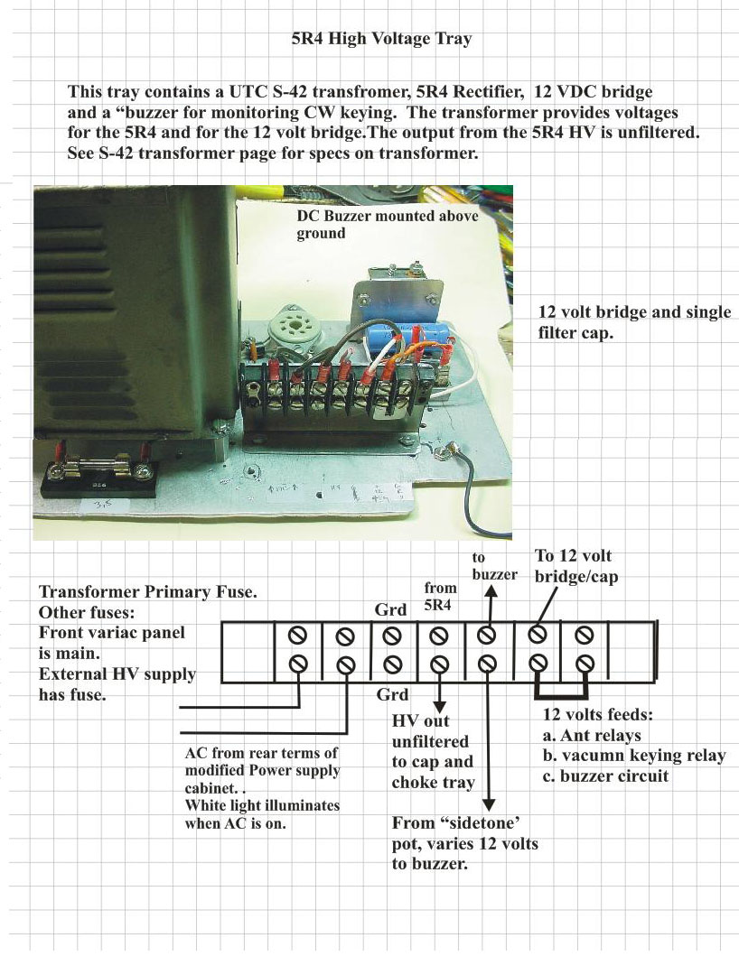
5R4 High Voltage Tray provides the "low" high voltage and in addition I utilized a couple of the filament windings on my UTC S-42 transformer and a small bridge rectifier block to provide DC for the relays. The 5R4 voltage feeds the Capacitor Choke tray.
On the original GP-9
Rectifier the operator could monitor his keying via a jacks J202 and J203
on the front of the control panel, a sample of the 800 cycle output was
taken from a winding on T203. I maintained this monitoring feature by
keying a small adjustable DC buzzer and coupled the buzzer to the jacks
via the original variable resistor R203 and R 204. The buzzer could also
be heard without head phones.
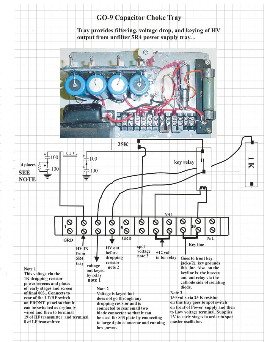
This tray
contained the capacitors and chokes for the 540 volt supply for oscillator,
intermediate amplifiers, and screen voltage for the final 803 amplifiers.
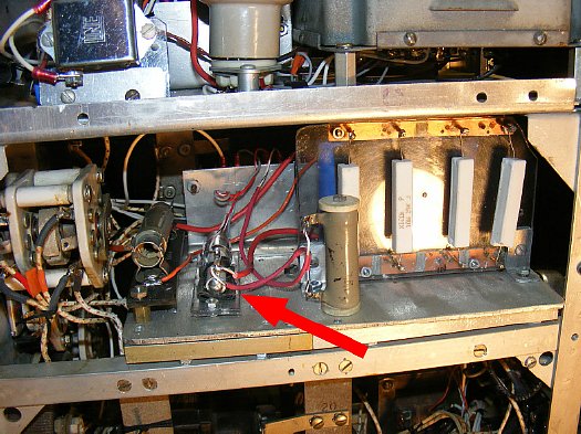
After
fooling around with several keying circuits I finally cheated and used
a vacuum relay to key the HV to the screen and plates of the early stages
and the screen of the final PA tube and 803. The 12 volt relay contacts
were rated at 12,000 volts. Purchased on ePay.
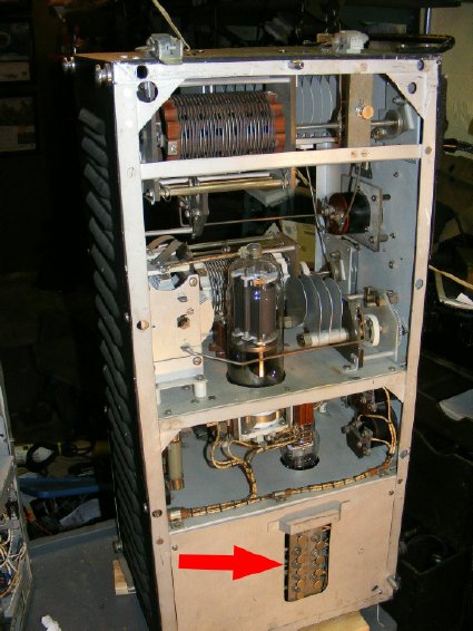
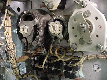
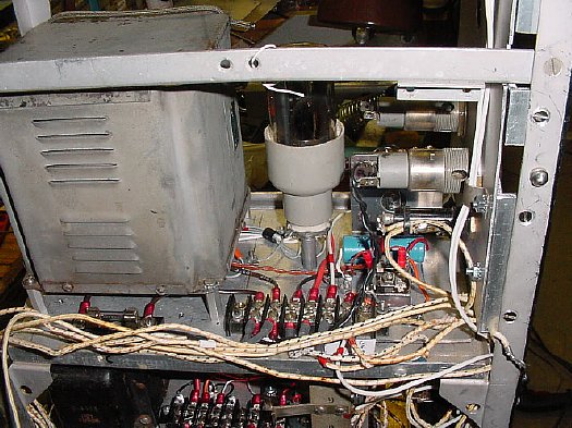
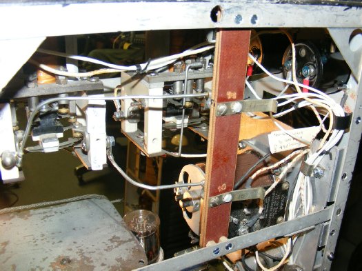
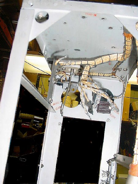
The contacts
at the bottom of the transmitter must be perfectly clean as they mate
with the contacts of the rectifier assembly shown below.
This photo depicts the contacts on the rectifier assembly, I had to borrow two of the unused contacts for a missing board at the top of the Rectifier.

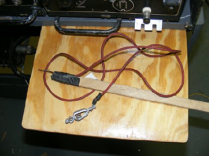
A
simple shorting stick should be used while working on the supplies.
The GO-9 transmitters
require 2000 volts, there was just not enough room in the Rectifier chassis
for a HV supply, it was decided to build one in a separate enclosure and
remote it.
Details
of the HV supply can be found here:
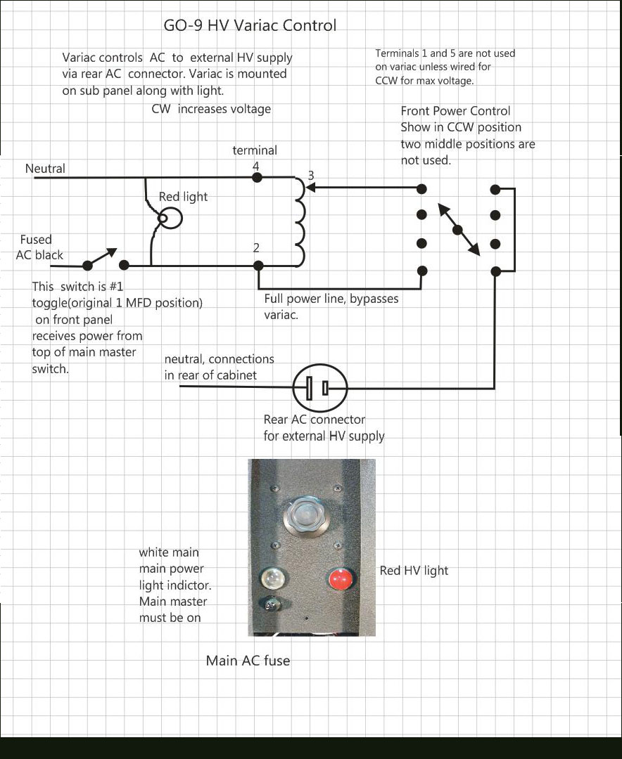
The 2000 volt
HV supply would be switched by the original wiring plus a variac was added
to vary the voltage to the final PA for different power settings.
A
sub panel was created for mounting the variac and two additional indicator
lights for AC Main and HV On.
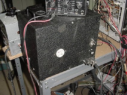
The
front of the "secret" variac sub panel. AC and HV lights
are on. Variac knob is above the lights.
The "secret" variac sub panel can be covered by the Rectifier access cover.
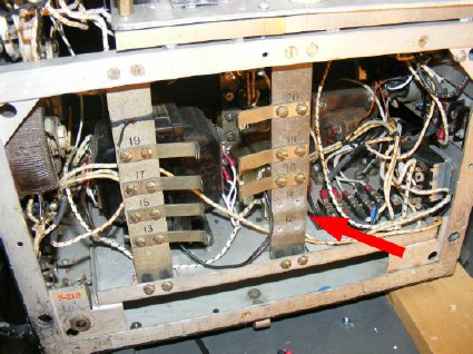
I had to "borrow" some unused contacts in order to fabricate an antenna strip for the low frequency transmitter.
A new contact
strip was fabricated from phenolic for the antenna connections for the
low frequency transmitter.
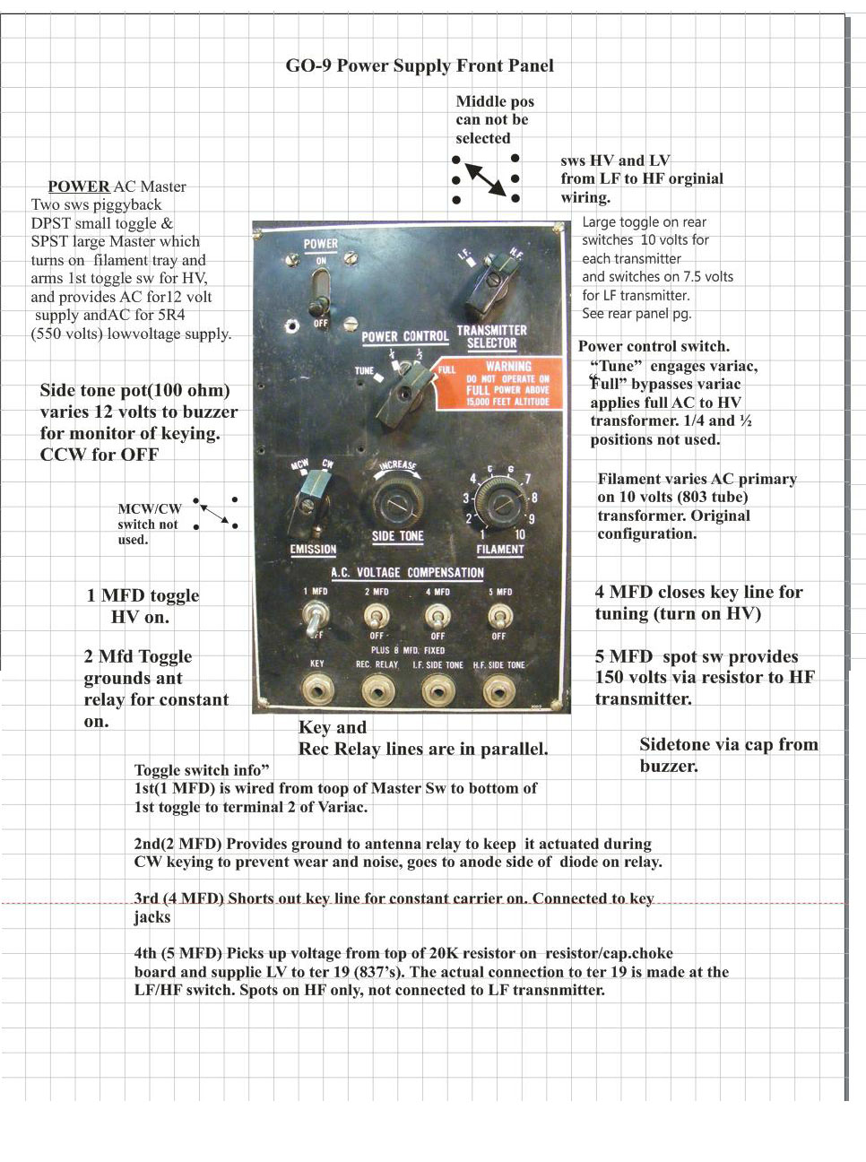
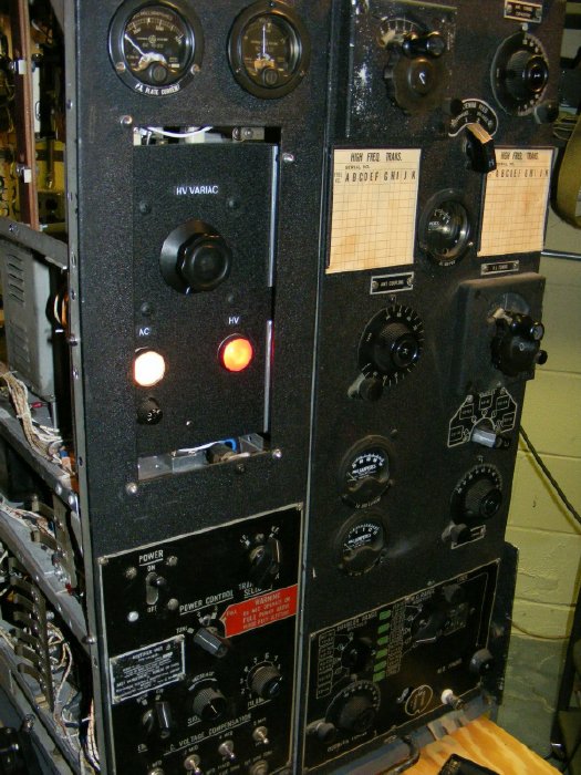
The majority of the controls and switches on the front panel function as designed. However the AC Voltage capacitor switches (toggle) were assigned alternate functions.
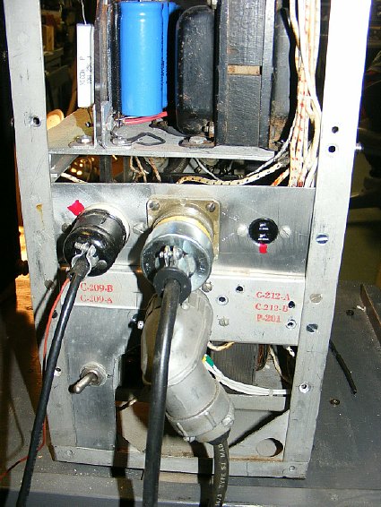
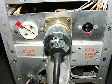
Rear panel. On the left
is the HV connector going to the remoted High Voltage supply. In the center
is the 120 VAC connector and on the right is a two pin Jones connector
going to the 5R4 supply.
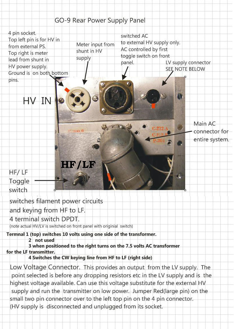
The rear panel
provides a lot of flexibility. The toggle switch provides switching from
HF to LF and is used in conjunction with the front panel switch.
The voltage from the
5R4 supply can be jumpered to the HV feed to the 803 final for low power
operation and for testing the low power stages. With this jumper the GO-9
can be operated barefoot without the remoted 2000 volt supply.
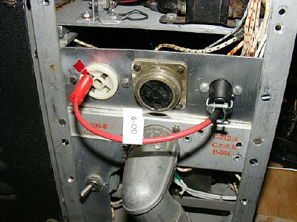
The jumper is shown for providing the 5R4 supply voltage to the final PA Tube.
I love it when a plan comes together.
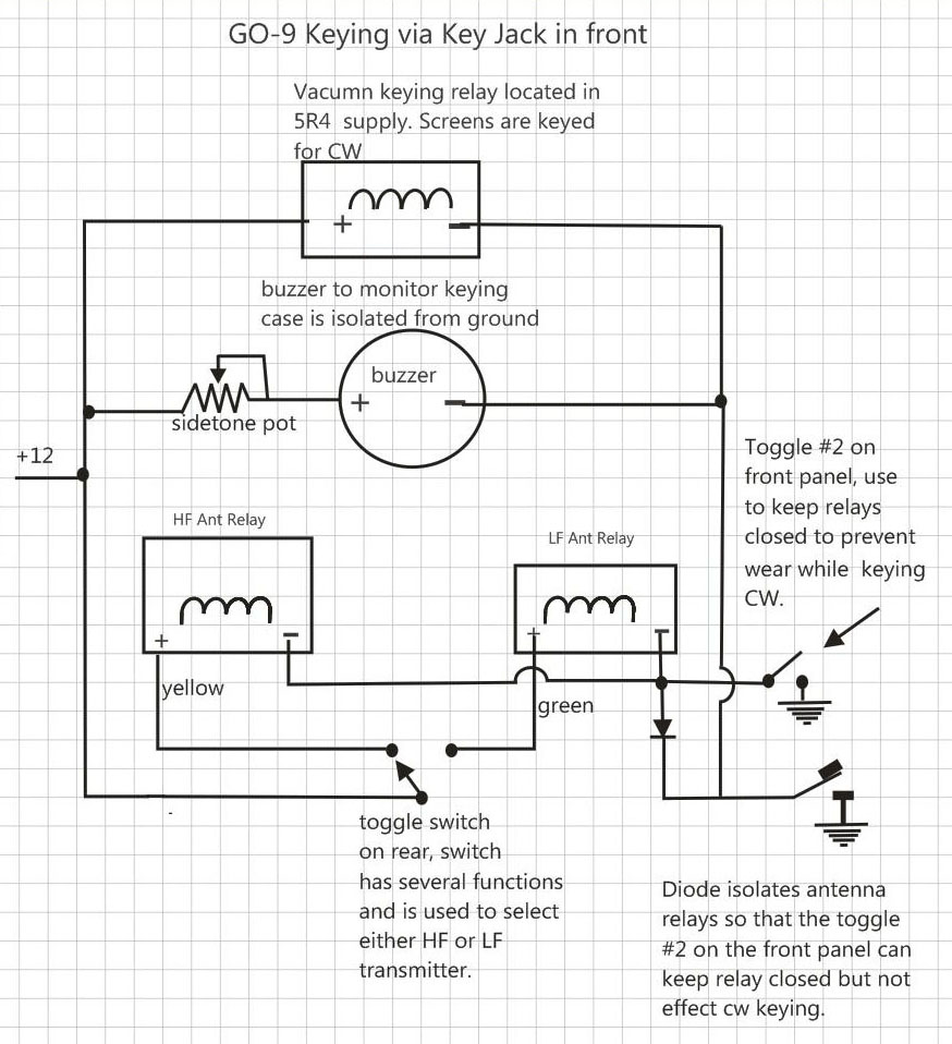
Here is my final
keying scheme. I key the two giant relays, side tone buzzer and the vacuum
keying relay. I quickly found that keying the antenna relays resulted
in some pretty bad key clicks so I used one of the front panel toggle
switches to keep the relays closed while transmitting. The toggle switch
on the rear panel selects which Antenna Relay would be utilized.
One of the previous owners decided he did not like the relays but he did leave the wiring intact with terminals on the ends and heavy buss wire.
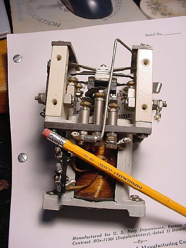
Since
the relays were missing so I contacted one of our MRCA members William
Donzelli. Also know as Toober on eBay. Bill has a lot of interested stuff.
His listing for eBay can be found:
http://www.ebay.com/sch/toober/m.html
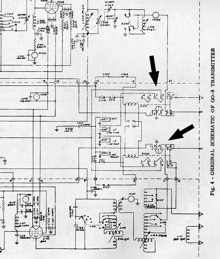
The
original relay circuits are"busy" really "busy"
A keying description from the Navy GO-9 Instruction book 31 December 1940:
"Keying of the transmitters is accomplished by means of Keying Relays K-201 and K-202 which are located in the rectifier Unit. Keying Relay K-201 is used for the High Frequency Transmitter while Keying Relay K-202 is used for the Intermediate Frequency Transmitter. Contacts #5, #6, #9, and #10 serve to transfer the antenna to the receiver and to the transmitter. In the de-engergized position contacts #9 and #5 are closed and the antenna is connected directly to the receiver antenna terminals on the Rectifier Unit. In the energized position contacts #6 and #10 are closed while contacts #5 and #9 are open, thus transferring the antenna to the transmitter for transmission. In addition, contacts #8 and #2 close and ground the receiver antenna terminal. Contacts#7 and #3 close and complete the circuits to the side tone jack. The grounding of contact #1 closes the grid return circuit of the master oscillator. The closing of contacts #4 and #11 applies power to the primary of the high voltage and low voltage transformers."

All most finished. Why is it that when you bundle wires with cable lacing that as soon as you are finished you have to make a change in wiring? Fini photos of the GO-9 project will be posted in the final segment of these GO-9 pages. BTW if you would like information on lacing and other construction topics you can down load the "Collins Quality Standards Manual" from K4OZY's Collins Repository".
http://www.jptronics.org/radios/Collins/Quality/collins_quality.1.pdf