 |
K4CHE GO-9 HF Transmitter Project "Don't ask me why, I just like to test stuff" |
 |
.JPG)
Chances are you will never see a very high RF amp meter indication while using your GO-9 HF Transmitter unless you have a very short or unusual antenna which exhibits a low radiation resistance or you have made a large error in tuning and placed the amp meter in the upper portion of a current loop.
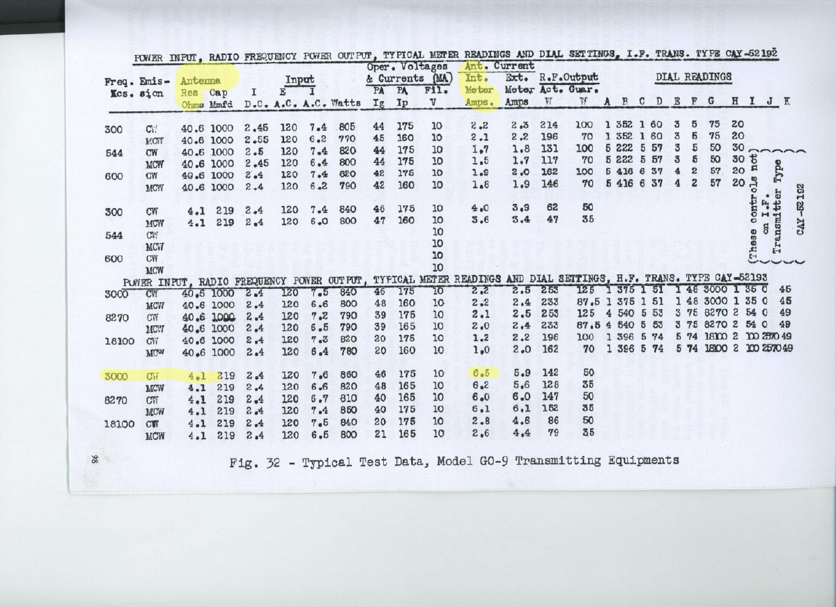
Figure 32 in the manual provides RF output indications for several frequency ranges. Note that for 3000 Kc with a Antenna resistance of 4.1 ohms the RF Antenna Current indication is 6.5 amps.
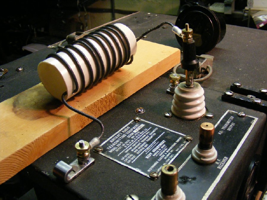
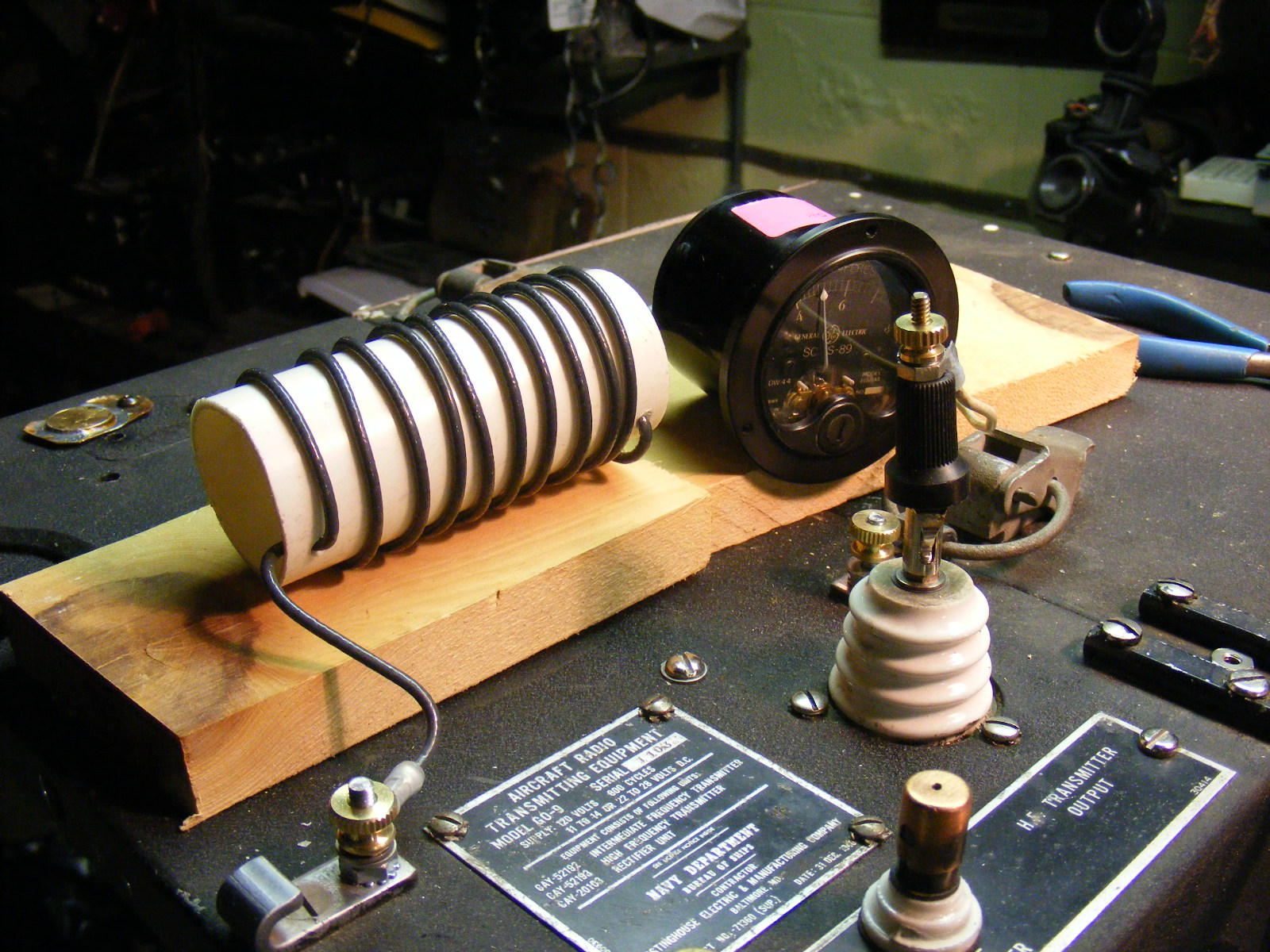
A coil "load" exhibiting a low resistance can be fabricated easily. I used a piece of wood as an insulator to keep the coil off of the cabinet. Turns are spread to prevent arcing.
DANGER HIGH VOLTAGE on the antenna terminals regardless
of the position of the Antenna Feed Switch.
Low
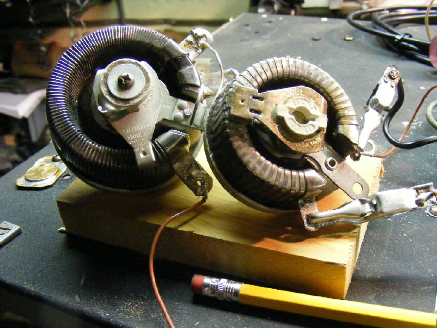
value-high wattage variable potentiometers can also be used to provide
a temporary low resistance load for testing of the RF Ammeter.
A
external "calibrated" RF Current meter can be placed in series
with the home made loading coil. In this case the meter in the photo was
checked previously for accuracy and this meter will be compared with the
actual GO-9 meter indication on the transmitter.
DANGER
HIGH VOLTAGE
A page describing RF Ammeter testing, shunts, and what to do when the thermocoupler goes bad can be found here.
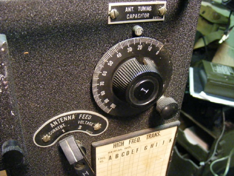
During
this "low resistance test be prepared to peak current with the ANT
TUNING capacitor.
Don't
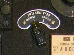
forget to position the Antenna Feed switch to CURRENT.
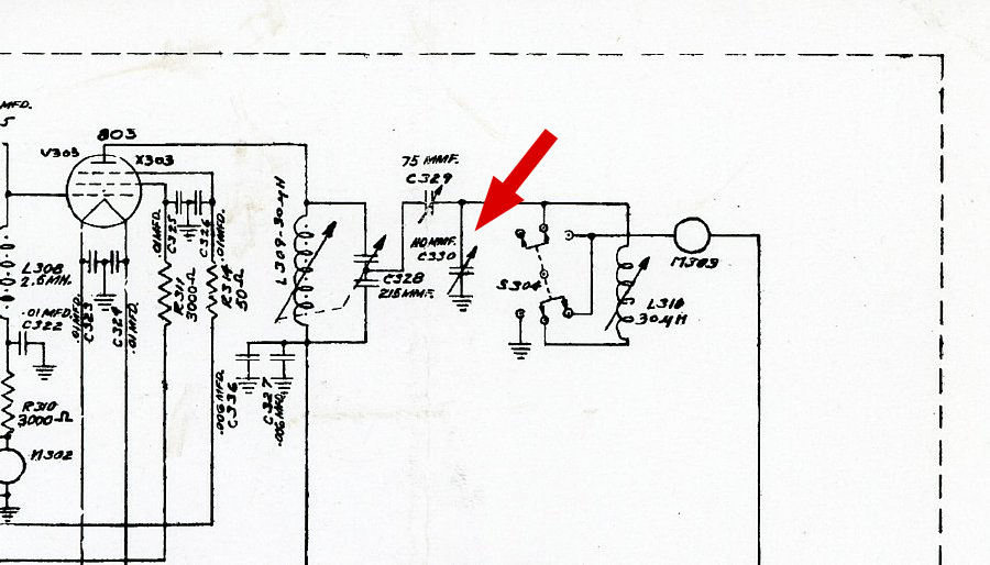
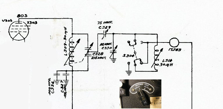
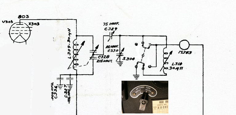
Red
arrow points to the ANT TUNING capacitor(C330). The Antenna Feed switch
(S304) feeds the RF meter and antenna.(discussed below)
Antenna
Feed Switch
Low
Impedance Antenna High
Impedance Antenna
Clete Whitaker, WB2CPN wrote: "The switch marked Voltage or Current could be relabeled High or Low Impedance looking into the antenna."
Additional Comments by Clete.
"Looking at the schematic drawing of the transmitter, three things I'll mention, but first I'll say that is the most versatile antenna tuner I can remember."
Video PA Tuning( Loading Coil)
1. "In the Current mode, C-330 and the Variable Inductor going to the meter, and then to the antenna, make up a series-resonant circuit, and is adjusted for Maximum current in the antenna. This could be high if the Impedance is low."
2. "In the Voltage mode, C-330 and the Inductor make up a parallel-resonant circuit. The top end of a parallel-resonant circuit is a very high Impedance to ground. Very high voltages can be found there. Again, C-330 is adjusted for Maximum current into the Antenna, which may not be much. We're talking high voltage, not high current."
3. "In some applications I've seen the antenna current meter shunted by a knife switch. They last longer, and why use it no one's reading it ?" Clete Whitaker
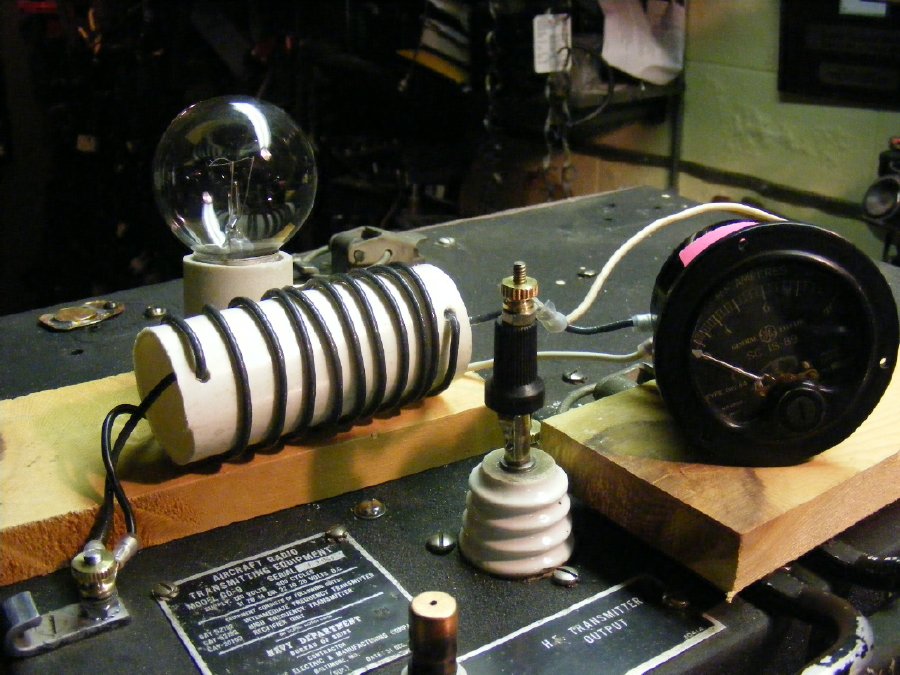
My favorite RF Ammeter test jig for the GO-9. A low wattage (25 watt)bulb in parallel with the coil load. The "clear" bulb assists in intial tuning as very low power levels can be visible.
.JPG)
The
low wattage bulb is "shunted" by the coil which prevents burning
out the bulb, the "parallel" coil and bulb assembly series feed
the external meter(previously checked for accuracy) which is connected
to the antenna post. Keep your wiring well insulated from the metal cabinet
top.
A another test jig providing a low impedance load can be fabricated by attaching a 10 feet section of RG-58 with the end unterminated - - - Ground the shield for safety and put the meter in series with the center conductor. But no light bulb . . .
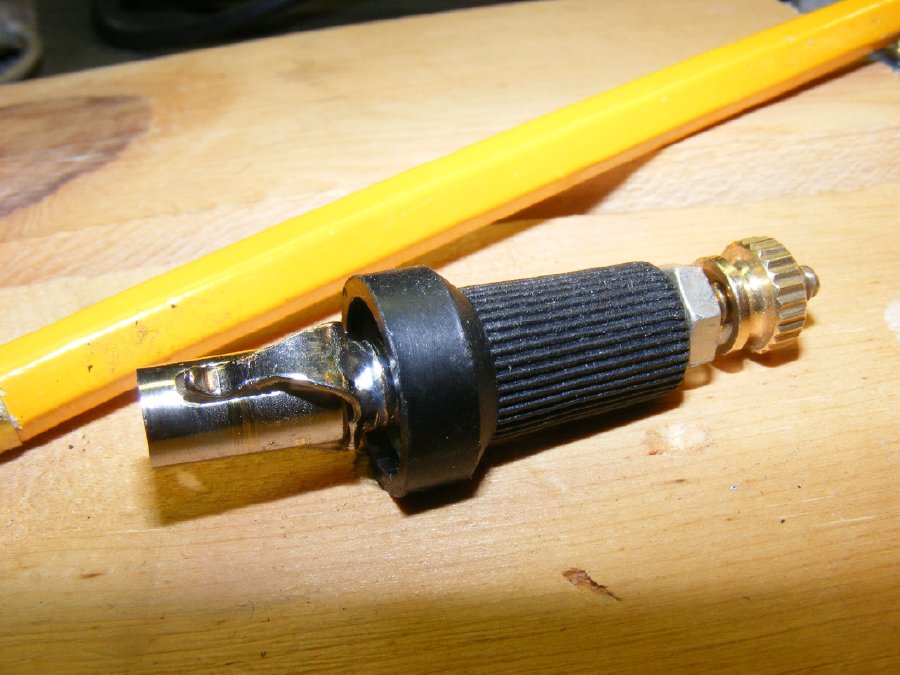
A binding post connector is handy. More on the connectors in the "Testing" Pages.
GO-9 Testing Pages
Return
to GO-9 Index
Return
to K4CHE Index